background image

Customer Service 1-888-707-1880 
or email [email protected]                                                          Dyaco Canada Inc. ©2014 


15

MAINTENANCE 

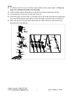
HOW TO ADJUST THE REED SWITCH 

If the console does not display correct feedback, the reed switch should be adjusted. To adjust 
the reed switch, the chain cover (42) must first be removed.   
Remove the left pedal (17L) from the crank (16). 
Remove the two self-tapping screws (43) from each side of chain cover (42). Remove another 
seven ST5 x 15 self-tapping screws (44) from right chain cover (42R). Remove the crank cover 
(41) from the chain cover (42). Hold the chain cover (42) near the back and pull it apart slightly 
until the chain cover can be lifted off the ends of the crank (16). 

Do not pull the chain cover 

apart at the top or the seam may be broken.


Next, locate the sensor wire (12). Turn the pulley until the magnet is aligned with the reed switch. 
Loosen, but do not remove, the ST5 x 15 screw (44). Slide the reed switch slightly toward or 
away from the magnet. Make sure that the magnet will not hit the reed switch. Retighten the 
screw (44). Turn the pulley for a moment. Repeat until the console displays correct feedback.  
When the Reed Switch is correctly adjusted, reattach the Chain Cover and the Crank Covers. 

1 7 R

1 7 L

4 3

4 3

4 4

4 4

4 4

4 4

4 4

4 4

4 4

5 0

1 2

4 2 1 6

4 1


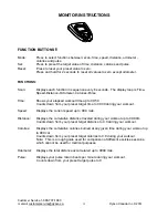
HOW TO ADJUST THE DRIVE BELT 

If you can feel the pedals slip while you are pedaling, even when the resistance is adjusted to the 
highest level, the drive belt may need to be adjusted. To adjust the drive belt, the Chain Cover 
(42) must first be removed.   
Next, loosen the France nut (52), and turn the Adjustment Bolt (55) counter-clockwise until the 
Drive Belt (63) is tight. Then, retighten the France nut (52).   
When the drive belt is correctly adjusted, reattach the Chain Cover and the Crank Covers. 

5 2

5 5

Summary of Contents for 16116305

Page 1: ...RECUMBENT CYCLE OWNER S MANUAL Model No 16116305 SIRIUS Recumbent Cycle CAUTION You must read and understand this owner s manual before operating unit Keep this manual for future reference...

Page 2: ...TENTS Manufacturer s Limited Warranty 2 Safety Precautions 3 Before you begin 4 Pre assembly Check List 5 Hardware Packing List 6 Assembly Instruction 7 11 Monitor Instruction 12 13 User Direction 14...

Page 3: ...ability of fitness for particular purpose are limited in duration to the first 12 months from date of purchase All other obligations or liabilities including liability for consequential damages are he...

Page 4: ...medical devise Various factors including the user s movement may affect the accuracy of the heart rate readings The pulse sensor is intended only as an exercise aid in determining heart rate trends in...

Page 5: ...read this manual carefully before you use the exercise bike If you have questions after reading this manual please see the front cover of this manual To help us assist you note the product model numbe...

Page 6: ...NO 62 NO 1 NO 4 NO 23 NO 25 NO 26 NO 6 NO 14 NO 27 PART NO DESCRIPTION Q TY 1 Main frame 1 2 Computer 1 4 Front post 1 5 Seat cushion 1 6 Back cushion 1 14 Front stabilizer 1 17L R Left Right pedal 1...

Page 7: ...needed to assemble this machine Before you start to assemble please check the hardware packing to make sure they are included Part No Description Qty Drawings 8 Allen screw M8 16 12 9 Curved washer 8...

Page 8: ...are kit check to see if it has been preassembled To avoid damaging parts do not use power tools for assembly STEP 1 Attach the front stabilizer 14 to the main frame 1 securing with two carriage bolts...

Page 9: ...Attach seat cushion 5 to seat support tube 26 securing with four allen screws 8 Attach back cushion 6 to seat support tube 26 securing with four allen screws 8 1 5 6 8 8 1 9 1 9 2 1 2 2 2 2 2 6 2 3 ST...

Page 10: ...on hand pulse wire 31 with front extension hand pulse wire 30 Connect extension sensor wire 10 with sensor wire 12 Insert front post 4 into main frame 1 and tighten with 4 sets of allen screw 8 and cu...

Page 11: ...nsion Connector in between the opening on the wire holder on the Lower Tension Connector Drop down the Connector so the fitting sits firmly on top of the bracket NOTE If you are not able to hold the F...

Page 12: ...on it Repeat for the left pedal 17L Note The right pedal should be threaded on clockwise and the left pedal on counter clockwise Attach bottle holder 62 to the front post 4 Securing with two self tap...

Page 13: ...out time up to 99 59 Counts down from your preset target time to 00 00 during your workout Speed Displays the current speed up to 99 9 mile Distance Displays the cumulative distance traveled during yo...

Page 14: ...art to count up If more than one value is preset the first to reach the value will sound the alarm Once you have stopped the alarm the next preset value will sound the alarm until you have reached all...

Page 15: ...he ends of the straps off the tabs on the pedals Adjust the straps to the desired position and then press the ends of the straps onto the tabs HOW TO MOVE THE EXERCISE BIKE To move the exercise bike g...

Page 16: ...pulley until the magnet is aligned with the reed switch Loosen but do not remove the ST5 x 15 screw 44 Slide the reed switch slightly toward or away from the magnet Make sure that the magnet will not...

Page 17: ...p for front stabilizer 2 16 1630516 Crank 1 17L 1630517L Left pedal 1 17R 1630517R Right pedal 1 18 1630518 End cap for seat support tube 2 19 1630519 Domed nut M8 8 20 1630520 Leveling pad 1 21 16305...

Page 18: ...lf tapping screw ST5 15 8 45 1630545 BB assembly 1 46 1630546 Bolt M8 55 1 47 1630547 Spacer for magnet assembly 2 48 1630548 Nylon nut M8 1 49 1630549 Magnet assembly 1 50 1630550 Sensor bracket 1 51...

Page 19: ...aco Canada Inc 2014 18 DIAGRAM 1 2 3 4 5 6 7 8 8 8 8 9 9 9 1 0 8 8 1 1 1 2 9 9 9 1 3 1 3 1 4 1 5 1 5 1 6 1 7 R 1 7 L 1 8 1 8 1 9 1 9 1 9 1 9 1 9 2 0 2 1 2 1 2 2 2 2 2 3 2 4 2 5 2 6 2 7 2 8 2 8 2 9 3 0...

Page 20: ...7 1880 or email customerservice dyaco ca Dyaco Canada Inc 2014 19 4 0 1 6 4 1 4 1 4 2 L 4 2 R 4 3 4 3 4 3 4 3 4 4 4 4 4 4 4 4 4 4 4 4 4 4 4 4 4 5 4 5 4 6 4 7 4 7 4 8 4 9 5 0 5 1 5 2 5 2 5 3 5 4 5 5 5...

Page 21: ...g wires into the back of the monitor Hand pulse defective Replace hand pulse grip Monitor not working properly Replace monitor Grinding Crank bearing defective Replace crank bearings Flywheel defectiv...

Page 22: ...ical fitness It is the efficient functioning of the heart and lungs Aerobic Fitness The largest amount of oxygen that you can use per minute during exercise is called your maximum oxygen uptake MVo2 T...

Page 23: ...ou are fitter you will need a higher threshold of stimulation To begin with you should exercise at a level that elevates your heart rate to about 65 to 70 of your maximum If you find this is too easy...

Page 24: ...verall fitness level A confirmation that you are on the correct program is a very slight soreness in most major muscle groups This is quite normal and will disappear in a matter of days If you experie...

Page 25: ...right shoulder up toward your ear the stretch up the left side of your neck Next rotate for one count Then lift your left shoulder your head back for one count stretching your chin to up for one coun...

Page 26: ...as you knees towards the floor Hold for 15 counts can and hold for 15 counts HAMSTRING STRETCHES CALF ACHILLES STRETCH Sit with your right leg extended Rest the sole of Lean against a wall with your l...

Reviews: