


Sinar Photography AG - Farbhofstrasse 21 - 8048 Zürich/Switzerland
Phone +41 (0)44 217 80 30 - Fax +41 (0)44 217 80 50 - [email protected] - www.sinar.ch
13.10.10 - Seite 4
A
B
C
D
E
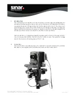
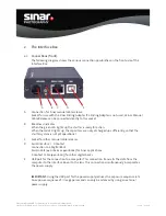
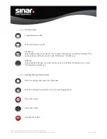
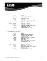
2. The Interface Box
2.1. Connections (front):
The following diagram shows the various connection possibilities on the front side of the
Interface Box.
A
Connection for Sinar manual cable release.
Socket for use with the Sinar Sliding Adapter. If a Sliding Adapter is not used, a Sinar Manual
Cable Release can be connected directly to this socket.
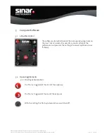
B
Readiness Indicator
When the green LED lights up, the shutter is ready for action.
When the red LED lights up, the capacitors are not yet charged up suffi ciently, so that the
shutter system is not yet operational.
C
Socket for other manual cable releases.
D
Serial Interface / X Contact
Connection to a Digital Back
Serial Cable (440.18.261 or 44018.262) for Sinar applications
X Contact Cable (440.18.263) for other digital backs
E
USB port for the connection to a computer. This connection transmits the data from the
computer to the Interface Box or to the lens. This connection simultaneously incorporates
the power supply.
IMPORTANT
: Using the USB port for the power supply reduces the exposure sequence rate.
An exposure sequence of 1 image per second can only be achieved by using an external
power supply.