background image

Simrad GC80/85 Double System Controller 


74


988-12721-001 

Alert detected in GC80/85 Expanded No.1


Alarm 

code 

Name 

Detailed code*1  Priority  Category  Troubleshooting 

300 

NO1GYRO MAIN PWR 

E-2 

Warning 

TS-24 

301 

NO1GYRO PWR FAIL 

E-2 

Warning 

302 

NO1GYRO INVERTER 

E-2 

Warning 

303 

NO1GYRO CONT. PWR 

E-2 

Warning 

304 

NO1GYRO ROTOR 

E-2 

Warning 

305 

NO1GYRO LEVEL 

E-2 

Warning 

306 

NO1GYRO SERVO 

E-2 

Warning 

307 

NO1GYRO EEPROM 

E-2 

Warning 

308 

NO1GYRO INN.COM1 

E-2 

Warning 

309 

NO1GYRO INN.COM2 

E-2 

Warning 

310 

NO1GYRO GPS COMM 

E-2 

Warning 

311 

NO1GYRO GPS DATA 

E-2 

Warning 

312 

NO1GYRO LOG COMM 

E-2 

Warning 

313 

NO1GYRO LOG DATA 

E-2 

Warning 

318 

NO1GYRO E5V 

E-2 

Warning 

319 

NO1GYRO STEP ERR. 

E-2 

Warning 

320 

NO1GYRO ZERO ERR. 

E-2 

Warning 

321 

NO1GYRO DGC COMM 

E-2 

Warning 


Alert detected in GC80/85 Expanded No.2 

Alarm 

code 

Name 

Detailed code*1  Priority  Category  Troubleshooting 

500 

NO2GYRO MAIN PWR 

E-2 

Warning 

TS-24 

501 

NO2GYRO PWR FAIL 

E-2 

Warning 

502 

NO2GYRO INVERTER 

E-2 

Warning 

503 

NO2GYRO CONT.PWR 

E-2 

Warning 

504 

NO2GYRO ROTOR 

E-2 

Warning 

505 

NO2GYRO LEVEL 

E-2 

Warning 

506 

NO2GYRO SERVO 

E-2 

Warning 

507 

NO2GYRO EEPROM 

E-2 

Warning 

508 

NO2GYRO INN.COM1 

E-2 

Warning 

509 

NO2GYRO INN.COM2 

E-2 

Warning 

510 

NO2GYRO GPS COMM. 

E-2 

Warning 

Summary of Contents for GC80 EXPANDED

Page 1: ...ENGLISH GC80 85 Double System Controller User Manual www navico commercial com...

Page 2: ......

Page 3: ...Simrad GC80 85 Double System Controller 988 12721 001 3 Document history Rev 001 First review...

Page 4: ...y or property damage The user of this product is solely responsible for observing maritime safety practices NAVICO HOLDING AS AND ITS SUBSIDIARIES BRANCHES AND AFFILIATES DISCLAIM ALL LIABILITY FOR AN...

Page 5: ...entions In this manual references to buttons on the operator panels are written in boldface but in a different text style e g MENU button SET ENT button HDG button Important text that requires special...

Page 6: ...pecifications Specifications for the system and for all separate units in the GC80 85 Double System Controller unit 8 Drawings Dimensional drawings and wiring diagrams for the GC80 85 Double System Co...

Page 7: ...ponents 12 2 4 Bearing repeaters 14 3 USER INTERFACE 15 3 1 General 15 3 2 Control panel 15 Heading sensor indicators 15 4 OPERATION 17 4 1 System start up and shut down 17 Power ON OFF 17 4 2 Display...

Page 8: ...heck 26 6 INSTALLATION 28 6 1 Unpacking and handling 28 6 2 Mechanical installation 28 Control unit 28 6 3 Cabling 29 Power supply 30 6 4 Grounding the unit 30 6 5 DIP switch and jumper settings 30 Ac...

Page 9: ...TERMINAL LAYOUT 48 10 1 DGCT board 48 TB1 48 TB2 48 TB3 49 TB21 50 TB22 50 TB23 51 TB24 52 TB25 53 TB26 53 TB27 54 TB28 54 TB29 55 TB30 55 11 DIP SWITCH SETTINGS 56 11 1 Double System Controller unit...

Page 10: ...reen 71 Check alert list and alert history 71 12 3 Complete alarm code lists 72 Alerts detected on Double 72 Alert detected in GC80 85 Expanded No 1 74 Alert detected in GC80 85 Expanded No 2 74 Alarm...

Page 11: ...al interface IEC Standard 61162 2 Ed 1 Maritime navigation and radio communication equipment and systems digital Interface Single talker and multiple listeners high speed transmission IEC 62288 Ed 1 P...

Page 12: ...pens any external equipment depending on the bearing output from GC80 85 Double System Controller unit should be operated manually or switched to other bearing sensors To assure long time safe operati...

Page 13: ...Simrad GC80 85 Double System Controller 988 12721 001 13 Note For details refer to TECHNICAL SPECIFICATIONS on page 34...

Page 14: ...e repeater backup function included in the Double controller unit The following serial signals may be selected Low speed GC80 IEC61162 1 ed 4 4800 and 38400 baud possible High speed GC85 IEC61162 2 ed...

Page 15: ...el 3 2 Control panel The control panel includes the buttons described on the following pages Heading sensor indicators NO 1 indicator Indicates the status of the NO 1 gyrocompass Green LED Normal oper...

Page 16: ...the cursor up This key is also used to select the NO 2 gyrocompass as the active heading reference source Refer to Select heading sensor on page 20 ACK key Used to acknowledge alerts buzzer stop SET E...

Page 17: ...r but the inner display uses a thin glass panel 4 1 System start up and shut down A GC80 85 Double System Controller unit is usually left with power ON If the system has to be shut down and restarted...

Page 18: ...u must follow the stop procedure explained in the GC80 85 Expanded MK2 User Manual 4 2 Display Start screen Turn on NO 1 gyrocompass NO 2 gyrocompass to start the unit The start up screen is displayed...

Page 19: ...f the connected heading sensor s is displayed The true heading of the selected heading sensor is displayed SELECTED Screen when the gyrocompass is settling 1 Select MAIN in the display menu list 2 Whe...

Page 20: ...O 1 gyrocompass press the NO 1 key and the HDG key simultaneously To select NO 2 gyrocompass press the NO 2 key and the HDG key simultaneously 4 4 Adjust display illumination and display test Adjust d...

Page 21: ...he keys Lights up at maximum brightness 3 Buzzer continuous sound 4 5 Alarm messages Central alarm panel On some installations it is required to connect the gyro to an external bridge alarm panel In t...

Page 22: ...ain purpose is to catch signs of system failure at an early stage Assign a person in charge of the system and perform checks and maintenance under his responsibility 5 2 Precautions Do not tap or hit...

Page 23: ...connectors should be checked by visual inspection only Push the connector plugs into the connector If the connector plugs are equipped with a lock ensure that this is in the correct position 5 6 Check...

Page 24: ...2 TB22 16 22_24V Power supply for ch 22 serial repeater XF3 TB22 21 23_24V Power supply for ch 23 serial repeater XF4 TB23 2 24_24V Power supply for ch 24 serial repeater XF5 TB23 7 25_24V Power suppl...

Page 25: ...switch breaker fed from the vessel s power AC DC power 2 If a fuse is blown check the cause Even though it is replaced with the same capacity fuse and it works the fuse is blown again unless the cause...

Page 26: ...Keep corrosive gas breed bacteria insects or small animals away from the storage area 4 Cover the system with plastic sheets or equivalents to keep away dust 5 When welding works are carried out near...

Page 27: ...27 3 Press NO 2 key or EXT key and move the yellow frame to the selected heading sensor 4 Press SET ENT key to display the heading of the gyrocompass rate of turn latitude and vessel s speed input Rat...

Page 28: ...dling Care should be taken when unpacking and handling the equipment A visual inspection should be made to see that the equipment has not been damaged during shipment and that all components and parts...

Page 29: ...rom the remote mounting kit to the Control unit front door 3 Mount the Control panel in the mounting frame from the remote mounting kit using 4 screws The mounting frame must already be mounted in the...

Page 30: ...2 switches on the SCC board in the control unit no switches have to be set when installing the system These 2 switches are set to configure the control unit to match the type of gyro system GC80 or GC...

Page 31: ...Simrad GC80 85 Double System Controller 988 12721 001 31...

Page 32: ...tion is done by S1 8 on the DGCIF board located under the DGCT board Manual switching Automatic switching 6 7 Expanded Control unit settings in a Double gyro system When the Expanded Control unit is u...

Page 33: ...NT key to display the setting parameters 4 Press SET ENT key The setting value starts blinking 5 Press NO 2 or EXT key to change the value 6 Press SET ENT key to confirm the setting value PARAMETER DE...

Page 34: ...e of turn display True heading output Rate of turn output Alert history details display Display Unit Size 3 5 inches Effective display range 70 56 mm x 52 92 mm Resolution 320 x 240 dot QVGA Dot pitch...

Page 35: ...signal GPS Circuits 2 Electrical RS422 NMEA0183 Baud rate 4800 bps Data bits 8 bits Parity None Stop bits 1 Transmit freq 1 Hz Input format GGA x xx x N xx x E x hh CR LF GLL xxxx xx N xxxx xx E hh CR...

Page 36: ...bits 1 Transmit freq INDETERMINATELY Input format ACN xxxxxx xx aaa x x x x a C hh CR LF HBT x x a x hh CR LF PULSE signal LOG Circuits 1 Electrical 200 400 p p n m dry contact Voltage Current 5 V 5 m...

Page 37: ...x a hh CR LF Data no 4 HEHCR x x a a x x hh CR LF Data no 5 HENSR a A hh CR LF Data no 6 PTKM HEALM xxxx x xx hh CR LF INS BAMS Circuits 1 Electrical RS422 NMEA0183 Baud rate 4800 38400 bps Data bits...

Page 38: ...DIP switch settings on page 18 Running Circuits 1 Voltage Current 24 V 1 A All alarms Circuits 1 Voltage Current 24 V 1 A Refer to Jumper settings on SCC board on page 64 7 4 Physical dimensions GC80...

Page 39: ...roller 988 12721 001 39 7 6 Environmental specifications GC80 85 Double System Controller unit Enclosure material Aluminum Environmental protection IP22 Color Black Temperature range Operating 15 55 C...

Page 40: ...ons of the Double System Controller unit together with wiring diagrams of the gyro system 8 1 Drawings included The following mechanical drawings are enclosed Name Rev GC80 85 Double System Controller...

Page 41: ...Simrad GC80 85 Double System Controller 988 12721 001 41 Double System Controller unit dimensional drawing Remote panel dimensional drawing...

Page 42: ...Simrad GC80 85 Double System Controller 42 988 12721 001...

Page 43: ...Simrad GC80 85 Double System Controller 988 12721 001 43...

Page 44: ...Simrad GC80 85 Double System Controller 44 988 12721 001...

Page 45: ...Simrad GC80 85 Double System Controller 988 12721 001 45...

Page 46: ...Simrad GC80 85 Double System Controller 46 988 12721 001 Wiring when the Control panel is mounted outside the Control unit...

Page 47: ...roller unit 9 1 GC80 85 Double System Controller unit PART NO DESCRIPTION 000 15037 001 GC80 85 Double System Controller unit 988 12719 00x GC80 85 Double System Controller unit User manual 9 2 GC80 8...

Page 48: ...ignal output 4 G1TX 5 G1RX Internal communication serial signal input 6 G1RX 7 G1SC Internal communication serial signal GND 8 G1SEL1 Selection signal input potential free contact 9 G1SEL2 10 E1SEL1 E...

Page 49: ...signal output potential free contact 15 G2RNCN2 16 Not used TB3 PIN NO NAME DETAILS 1 P_RX Extension of operation panel internal communication serial signal input 2 P_RX 3 P_SC Extension of operation...

Page 50: ...selected sensor 14 15TX Serial signal output RS422 selected sensor 15 15TSC Serial signal output GND 16 16TX Serial signal output RS422 selected sensor 17 16TX Serial signal output RS422 selected sen...

Page 51: ...23_24 V Power for repeaters 24 V DC 22 24TX Serial signal output RS422 selected sensor 23 24TX Serial signal output RS422 selected sensor 24 24TSC Serial signal output GND TB23 PIN NO NAME DETAILS 1 2...

Page 52: ...t 3 phased selected sensor 2 STA2 Step to step signal output 3 phased selected sensor 3 STA3 Step to step signal 3 phased selected sensor 4 STA4 Power for repeaters GND 5 STA5 Power for repeaters 24 V...

Page 53: ...o step signal output 3 phased selected sensor 12 STF2 Step to step signal output 3 phased selected sensor 13 STF3 Step to step signal 3 phased selected sensor 14 STF4 Power for repeaters GND 15 STF5 P...

Page 54: ...2 BNA2 13 BIN1 External alert acknowledging signal input potential free contact Buzzer stop 14 BIN2 15 MSPTX Serial signal output RS422 Spare 16 MSPTX Serial signal output RS422 Spare TB28 PIN NO NAME...

Page 55: ...l signal GND 13 LG1P1 NO 1 SDME vessel speed pulse input 200 P NM 14 LG1P2 NO 1 SDME vessel speed pulse input 200 P NM 15 LG2P1 NO 2 SDME vessel speed pulse input 200 P NM 16 LG2P2 NO 2 SDME vessel sp...

Page 56: ...t that include jumpers and DIP switches 11 1 Double System Controller unit 3 different boards in the Double System Controller unit have jumpers and or DIP switches that may be used to configure the GC...

Page 57: ...wnload E4 1 2 short NO 2 setting of speed log pulse 1 2 short 200 p p n m contact 3 4 short 400 p p n m contact E5 Open CPU U1 reset CPU reset short for CPU reset E6 Short DGCIF U1 software download S...

Page 58: ...S2 1 ON NO 1 AMS connection OFF No connection ON Yes S2 2 OFF NO 2 AMS connection OFF No connection ON Yes S2 3 OFF Pilot connection Do not touch S2 4 OFF BNWAS connection Do not touch S2 5 OFF Do not...

Page 59: ...1 gyrocompass serial output setting Output port DGCIF board TB21 18TX NO 1 OFF IEC61162 1 ed 4 output 4800 bps ON IEC61162 2 ed 1 output 38400 bps S11 7 OFF NO 1 gyrocompass serial output setting Outp...

Page 60: ...2 gyrocompass serial output setting Output port DGCIF board TB21 14TX NO 2 OFF IEC61162 1 ed 4 output 4800 bps ON IEC61162 2 ed 1 output 38400 bps S21 3 OFF NO 2 gyrocompass serial output setting Outp...

Page 61: ...Output port DGCIF board TB22 24TX NO 2 OFF IEC61162 1 ed 4 output 4800 bps ON IEC61162 2 ed 1 output 38400 bps S22 5 OFF NO 2 gyrocompass serial output setting Output port DGCIF board TB23 25TX NO 2...

Page 62: ...Dual S1 41 OFF Active gyro system Note Different settings for SSC board 1 and SSC board 2 Refer to footnote below S1 4 ON S1 5 OFF External sensor connection SW1 5 OFF No external sensor SW1 6 OFF SW1...

Page 63: ...gnal transmit frequency IEC61162 1 ed 4 SW2 5 OFF 1 sec 1 Hz SW2 6 OFF SW2 5 OFF 100 msec 10 Hz Note If selecting 38400 baud rate for the serial out the output frequency will be 50 Hz for HDT THS and...

Page 64: ...top enabled S4 1 OFF Not used Factory operation S4 2 ON For Double System or not OFF Standard ON Double S4 3 OFF Not used S4 4 OFF Alarm detection time OFF 300 ms ON 2 sec S4 5 OFF Enable disable THS...

Page 65: ...t the same time J9 1 2 short Jumper for sensor selection signal 1 2 short Normal open Short for selection 3 4 short Unused J10 1 2 short Jumper for sensor selection signal Output port GTERM A board RN...

Page 66: ...wo GPS signal connected Both jumpers shorted one GPS signal connected E2 1 2 short 3 4 short Connection of LOG to Double control unit NMEA0183 Both jumpers open two LOG signal connected NMEA0183 Both...

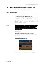
Page 67: ...in the LCD to indicate that several alarm situations are present The last activated alarm will be displayed on the right side of the display The figure below shows that alarm codes 1 3 and 2 were gene...

Page 68: ...t details date and cause press MENU NO 1 and select ALERT For more details refer to Complete alarm code lists on page 72 Alert history In the alert details you can check the priority the date and the...

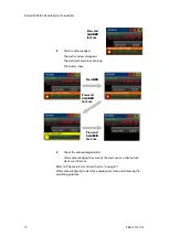
Page 69: ...ction explains the display and operation of the system when an alert is activated 1 Alert is activated An alert window appears in the display s lower bottom line The total number of alerts is shown in...

Page 70: ...ing the cause of the alert you can check which alerts are still active Refer to Check alert list and alert history on page 71 After acknowledging the alert take appropriate measures following the oper...

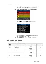
Page 71: ...NO 2 key or the EXT key to move the yellow frame to ALERT and press the SET ENT key to confirm 3 Active alerts are displayed in chronological order with the most recent ones at the top Check alert li...

Page 72: ...4 Press the SET ENT key to check archived alerts The screen automatically returns to the main screen if there is no key operation for 30 seconds or more 5 Press the MENU NO 1 key to go back to the cu...

Page 73: ...O 1 12 V E 2 Warning B TS 17 117 IF PWR NO 1 12 V E 2 Warning B 118 IF PWR NO 2 12 V E 2 Warning B TS 18 119 IF PWR NO 2 12 V E 2 Warning B 120 SENSOR SWITCH TS 19 123 NO 1 SCC WDT Caution B TS 20 124...

Page 74: ...arning B 311 NO1GYRO GPS DATA E 2 Warning B 312 NO1GYRO LOG COMM E 2 Warning B 313 NO1GYRO LOG DATA E 2 Warning B 318 NO1GYRO E5V E 2 Warning A 319 NO1GYRO STEP ERR E 2 Warning A 320 NO1GYRO ZERO ERR...

Page 75: ...on Indication Buzzer sound High A Alarm Alarm requires immediate attention and action The operator should switch to manual steering because the automatic steering may be unavailable Red 3 short beeps...

Page 76: ...em Controller 76 988 12721 001 Category A Alarm that can only be acknowledged ACK button by operating the system Category B Alarm that can be acknowledged ACK button by operating either the system or...

Page 77: ...he working condition of the NO 1 gyrocompass 2 If the NO 1 gyrocompass is abnormal fix the abnormality by following the operator manual of the gyrocompass Relevant information If an alert or symptom c...

Page 78: ...rn ON all of the switches again Relevant information If an alert or symptom cannot be fixed contact SIMRAD service center TS 11 Power supply interruption or power failure from the NO 1 gyrocompass con...

Page 79: ...or symptom is not fixed contact SIMRAD service center TS 16 Power failure of the internal communication system of Double Procedure and treatment 1 Check the fuse XF103 in the system Relevant informat...

Page 80: ...ng information of the heading sensor selected by the system Relevant information The alert is cleared by restarting the system Perform it when the vessel is at anchor TS 21 Gyrocompass integrity faile...

Page 81: ...heading of selected gyrocompass Relevant information If an alert or symptom is not fixed contact SIMRAD service center TS 24 Gyrocompass abnormality Procedure and treatment 1 Refer to the troubleshoo...

Page 82: ......

Page 83: ...988 12721 001...

Reviews:

Related manuals for GC80 EXPANDED