Simrad AP14 Manual Download Page 10

Page 19

Page 18

voir is kept topped up while doing this.  

NOTE

- Running the pump dry for more than a few
seconds can damage it. The hoses running to
the pump must be primed by following steps
6 to 9.

13.  After completing the cycle with each helm
position to the lowest position (including the
SRP12 pump) loosen the bleed valves (or the
hose fittings if there are no bleed valves) on the
ram cylinder one at a time, allowing air to bleed
out until a steady stream of oil comes out of the
bleeder with no air bubbles.  Drain at least 

1

2

litre

(1 pint) of oil to ensure all air is purged from the
system.  Retighten the bleed valve.
14.  Check the reservoir level.  If it is less than
half full, depressurise the system, remove the
filler cap and top up the oil level.  Pressurise the
system until the manufacturer’s recommended
pressure is reached.
15.  Repeat steps 10 to 14, turning each helm in
the opposite direction.
16.  Retighten the two relief valve screws.
17.  Turn one of the helms hard over.
18.  Open the bleed valve/fitting on the ram
cylinder at the end that the ram is 

extended

from.  Bleed until there is a steady stream of oil
with no air bubbles (Fig 4.9).  Retighten the
bleed valve.
19.  Turn the helm hard over in the opposite
direction.  Repeat step 18, opening the opposite
bleed valve this time (Fig 4.10).
20.  Check the reservoir fluid level - leave  reser-
voir 

1

2

to 

2

3

full.

21.  Pressurise the system until the manufactur-
er’s recommended pressure is reached.
22.  The manufacturer’s instructions should
give details of the correct number of turns lock
to lock when the system is properly bled.  An
excessive number of turns indicates that there is
still air in the system.

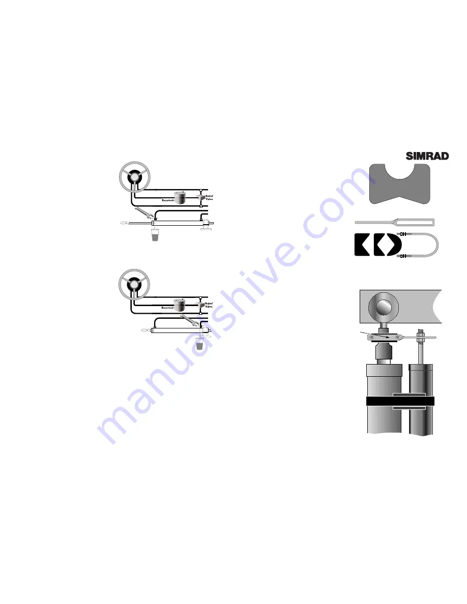
Fig 4.9 - Bleeding first hydraulic line

Fig 4.10 - Bleeding second hydraulic line

Fig 4.13 - Ram mounting using fixing kit

4.3  Linear Feedback Unit SLF12

The Linear Feedback Unit SLF12 measures the
rudder position and can be installed on most
types of boat, including I/O or Outboard dri-
ves.  It is important that the SLF12 is properly
installed with the maximum possible stroke
(minimum 150mm [6.0 in]), or it will not give an
accurate reading.

The SLF12 is mounted onto the hydraulic ram
cylinder using two mounting saddles (Fig 4.11).
Make sure that the maximum stroke of the
hydraulic ram is less than the 300 mm (12.0 in)
maximum stroke of the SLF12.  The saddles
support the SLF12 body, and can then be posi-
tioned on the back of the ram cylinder.  Check
that the SLF12 and ram are exactly parallel.
Use the cable ties supplied to secure the SLF12
and saddles onto the ram.

The SLF12 rod is attached to the ram using the
fixing kit supplied (Fig 4.12).  Fit the U-bolt and
bracket to the ram, checking that it will not
interfere with the movement of the ram at any
point of steering.  Rotate the assembly until the
SLF12 rod can be fixed to the slot in the bracket
using the two nuts supplied (Fig 4.13)  

Refer to

section 6.3 before tightening the nuts.

When satisfied with the positioning, tighten the
U-Bolt nuts fully, and then turn the helm hard
over from lock to lock, checking that the SLF12
rod does not bend at any time - this means that
the SLF12 is not exactly parallel to the ram, and
should be adjusted accordingly.

If the SLF12 cannot be fixed to the ram as
described, an accessory kit is available separate-
ly (part 

LFK500

) which can be ordered through

your local Simrad agent.  This contains a sepa-
rate mounting foot and balljoint assembly for
the end of the feedback rod, allowing the SLF12
to be independently fixed to the rudder arm.

• 

Do not fix the SLF12 directly to the rudder

arm if it is attached to the ram using the
mounting saddles, as the feedback rod will
bend when the rudder is at full lock.

• If connecting to a Teleflex HC5345 steering
cylinder the optional LFKSeastar kit should
be ordered.

FIg 4.11 - Mounting saddles (x 2)

Fig 4.12 - Fixing kit

Rudder Arm

Ram Cylinder

Cable Tie

SLF12

Fixing
Kit

Summary of Contents for AP14

Page 1: ...Manual Simrad AP14 Autopilot ...

Page 2: ... Mode 2 5 Set Key 2 6 Dodge 2 7 Backlighting 2 8 Alarms 2 8 1 Off Course Alarm 2 9 Default Boat Speed 2 10 Adjusting Dodge Angle 3 Parameter Adjustment 3 1 Rudder Movement Gain 3 2 Seastate 3 3 Autotrim 4 Installation AP14H Hydraulic Drive 4 1 Pump Installation SRP12 4 2 Bleeding The Steering System 4 2 1 Two or Three Line Systems 4 2 2 Pressurised Systems 4 3 Linear Feedback Unit SLF12 4 4 Fittin...

Page 3: ...ccurate and dependable steering in varying sea conditions with minimal current consumption The AP14 a state of the art autopilot system with many advanced features is simple to operate and occupies little space on the dash The keypad accesses all functions and pilot status is indicated clear ly in the backlit LCD display To ensure the best results from your autopilot it is essential that the unit ...

Page 4: ...Mode The AP14 has an inbuilt interface which allows it to be connected to NMEA0183 compatible equipment such as GPS LORAN Chart Plotters etc Once connected the AP14 can steer using data from this source in addition to the compass allowing a highly accu rate course to waypoint To enter Nav Mode the pilot must be in Auto Mode and receiving waypoint or route data from the navigational receiver Press ...

Page 5: ...o toggle the alarm on and off press and hold the Alarm FIg 2 8 Dodging to Starboard Press hold Fig 2 9 Selecting backlighting level Page 8 key Fig 2 10 The alarm icon will be displayed while the alarm is on If the off course alarm sounds press Alarm to acknowledge and disable the alarm The off course limit can be set from 10 60º Press Set see section 2 5 until ALARM appears at the bottom of the di...

Page 6: ... take a minute or so to fully compensate after a major course change Fig 3 3 Seastate deadband Average Course Fig 3 5 Autotrim principle COURSE HELD WIND TIDE Autotrim applied C o u r s e W i t h o u t A u t o t r i m Page 10 Page 11 3 Parameter Adjustment The AP14 uses highly advanced steering soft ware which constantly assesses how the boat is being affected by the sea conditions By adjust ing i...

Page 7: ...of the cylinder unbalanced rams have the rod emerging from one end only Fig 4 1 Volume 3 142 x S R2 r2 S Stroke length R Cylinder bore radius r Push rod radius If S R and r are in inches the volume will be in cubic inches in3 If they are in centimetres then the volume will be in cubic centimetres cc An ideal location for the pump is in a gas inflammable vapour free area where it will not be immers...

Page 8: ... not important which way round the pump outlet connections A B are connected to the steer ing lines as the pilot automatically sets the correct polarity when the unit is configured 4 2 Bleeding The Steering System The hydraulic system should be bled according to the manufacturer s instructions Make sure the cor rect oil is used to fill the system If there are no manufacturer s instructions availab...

Page 9: ...uence FLYBRIDGE 1 Helm CABIN 2 Second Helm ENGINE BAY 3 SRP12 Page 16 7 Turn the helm clockwise until the ram is fully extended 8 Open the bleed valve on the ram cylinder nearest to the extended ram If there are no bleed valves fitted to the cylinder loosen the nut connecting the hydraulic hose to the cylin der to allow the air to escape Do not com pletely undo the bleed valve or nut 9 Holding the...

Page 10: ... Unit SLF12 measures the rudder position and can be installed on most types of boat including I O or Outboard dri ves It is important that the SLF12 is properly installed with the maximum possible stroke minimum 150mm 6 0 in or it will not give an accurate reading The SLF12 is mounted onto the hydraulic ram cylinder using two mounting saddles Fig 4 11 Make sure that the maximum stroke of the hydra...

Page 11: ...e 20 Fig 4 14 Connecting control unit Length of Cable Run Under 5M 16 6Ft 5 10M 33 3Ft Cross Section Area 2 5mm2 4mm2 Conductor Type 50 0 25 56 0 3 AWG 13 12 Fig 4 17 Cable selection table Fig 4 16 Mounting Course Computer 4 6 Fitting Course Computer SCP12 Locate the course computer in a moisture heat and vibration free area somewhere between the boat s power source and the pump to minimise power ...

Page 12: ...ecting the AP14 to the power supply always check that the pilot and the receiver are not connected to a different battery bank This is to avoid a possible voltage drop between the interfaced equipment which would render the equipment inoperative The receiver must be running an active route or waypoint for the Nav Mode function to operate While any NMEA0183 compatible receivers should interface wit...

Page 13: ...to the boat the fol lowing basic requirements must be met 1 The boat must have at least one single cable steering helm Dual cable systems which are for high performance boats or boats over 11m 35 Ft cannot be adapted for the AP14R However the AP14R can be fitted to boats with two steering positions providing that one has a single cable helm 2 There must be a minimum of 250mm 10 0 in clearance behi...

Page 14: ...nnected Fig 5 5 Fit take up tube to the exit port and replace retaining bolt Page 26 the drive unit and wind it in by turning the steering shaft The cable should wind into the drive unit and emerge through the exit port into the take up tube Fig 5 6 Push the cable outer retainer into the entry port and refit the retain ing bolt to hold it in place Position the drive unit behind the dashboard and b...

Page 15: ...objects such as stereo speakers heating units etc If the boat has a metal hull this includes fer rocement the compass must be mounted above decks on a mast or pole between one and two metres 3 to 7 feet above deck When mounting make sure that the compass is the right way up and is level The compass unit can be screwed to a vertical bulkhead using the two No 6 x 3 4in self tapping screws provided I...

Page 16: ...ting the AP14 to the power supply always check that the pilot and the receiver are not connected to a different battery bank This is to avoid a possible voltage drop between the interfaced equipment which would render the equipment inoperative The receiver must be running an active route or waypoint for the Nav Mode function to operate While any NMEA0183 compatible receivers should interface with ...

Page 17: ...ent carrying cables or other magnetic electronic equipment to avoid deviation 3 Has the compass been mounted as near as possible to the centrepoint of the boat to min imise heel angle HYDRAULIC PUMP AP14H ONLY 1 Have the correct fittings been used 2 Has return line R been fitted from the pilot pump 3 Are check valves fitted if needed 4 Has the system been correctly bled of air 5 Is the tubing to t...

Page 18: ...uto to engage the autopilot and lock onto the heading in calm conditions a constant heading should be held 3 Alter course to Port and Starboard the course change should be smooth without any sign of overshooting 4 Look back at the wake of the boat to get an indication of the steering performance over a dis tance of at least 3km 2 Miles If there is any evidence of snaking or S ing try decreasing th...

Page 19: ...Low Gain AP14H only AP14R only Page 36 Page 37 7 Appendix 7 1 Advice On Operation When making course changes be aware of the effect of a large course change on the boat espe cially when travelling at high speed the AP14 will respond very quickly to any instructions so it is advisable to reduce speed before changing course This should particularly be remembered when approaching a waypoint in Nav Mo...

Page 20: ...der the black cover of the SRD12 Drive Unit can be used to identify the potential source of the problem Flashes Diagnosis Fault Location 5 Control unit not connected SHC14 6 No compass data received SHS12 7 No compass controls detected SHC14 SHS12 SRD12 8 Compass calibration failed SRD12 Page 38 7 5 Optional Accessories The following optional accessories for the AP14H and AP14R are available from ...

Page 21: ...cally Linear Thrust 175kg 385 lbs Max Torque 19 5Nm 170 lb in Speed 15 rpm Page 40 25 mm 1 0 in 65 mm 2 56 in 155 mm 6 33 in 7 7 Service Warranty This unit is guaranteed for 2 years from date of retail sale If it is necessary to have the unit repaired return it carriage prepaid to the agent in the country of purchase with a copy of the receipted invoice showing the date of purchase Where possible ...

Page 22: ......

Page 23: ...d Navico Star Lane Margate Kent CT9 4NP United Kingdom Telephone 44 0 1843 290290 Telefax 44 0 1843 290471 E Mail sales simrad navico co uk W O R L D W I D E M A N U F A C T U R E R O F M A R I N E E L E C T R O N I C S ...

Reviews: