


6
3.56
90.7mm
3.93"
99.8mm
2.04"
51.8mm
0.52"
13.2mm
3.24"
82.3mm
1.76"
44.7mm
1.77"
45mm
3.62"
92mm
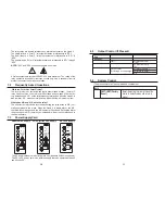
Engineering Label
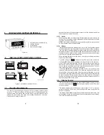
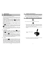
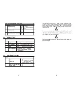
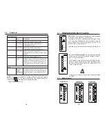
Figure 4-1. Installation and Panel Cutout
1.
Activated set point indicators (4)
2.
4-button Keypad
3.
Units Window
4.
Numeric and message
Figure 2-1
2.
DISPLAY AND KEYPAD CONTROLS
3.1
Mounting Requirements
The Hawk 3 Advanced Digital Controller 1/8 DIN counters require a panel
cutout of 1.77” (45mm) high be 3.62” (92mm) wide. To install the counter into
the panel cutout, remove the clips from the side of the meter. Slide the meter
through the panel cutout, then slide the mounting clips back on the meter.
Press evenly to ensure a proper fit.
3.
INSTALLATION AND PANEL CUTOUT
19
seconds the alarm will trip and remain in alarm until the display drops below
the setpoint for at least 2.5 seconds
9.1.3 Latch
When choosing
Ltch
, the relay output will latch immediately after crossing the
setpoint. The unit can then only be unlatched with a front panel reset or a reset
command from the RS-485 port.
NOTE:
If the display is still beyond the setpoint threshold, the reset will have
no effect and the unit will remain latched.
9.1.4 Alarm
The
Alr
mode allows choice between High, Low, or Off. The High Alarm means
that the display value must be greater or equal to the setpoint to go into Alarm.
The Low Alarm means that the display value must be less than or equal to the
setpoint to into alarm The Off Alarm means that all features of this setpoint is
disabled. No action will occur when display crosses a setpoint and the relays
will revert to a normally de-energized state.
When selecting
St
(State) from the menu, the display will alternate between
Stand the current setting.
To edit the setting press RE . Otherwise press
T
to move to the next choice.
If choosing
ND
(Normally De-energized) the relay will turn “on” the alarm con-
dition. This is a typical configuration. The one and two-relay outputs will act as
abeled; the normally closed contact will be closed until an alarm condition
occurs, and the opposite is true for the normally open connection. The four-
relay output only has the choice of normally open.
If choosing
NE
(Normally Energized) the relay will turn on at power up and
remain on until in an alarm condition. This mode can be used to create a fail-
safe condition or reverse the action of the four-relay configuration. In the fail-
safe example, the relay output would be wired to protect some device during
an alarm condition. During a power failure, the relay would be in the same
position as though it were in alarm thus protecting a device that may be on a
separate and possible active circuit.
9.2
Display Control
The next item that will appear in the menu is
Dctl
(Display Control). If this is
the item to be edited press
Enter
, otherwise press the down arrow
T
to move
to the next choice.
The display degrees, Deg, will allow you to select either °F or °C for the tem-
perature indication. There is no need to change this value if you prefer the
default °C indication.
The display refresh,
frsh,
will slow the numbers of updates to the display. This
setting ranges from as fast as 480 updates per minute (8 updates per second)
to as slow as 1 update per minute.
RESET
ENTER
RESET
ENTER
Summary of Contents for Hawk H340
Page 3: ...3 NOTES 22 NOTES...


