5-3
Chapter 5 Specifying Hardware Components
Specifying Hardware Components,
Continued
Adding Hardware
To add a hardware component to the programmer using click + add:
1. Right click in the Hardware component window. An action list appears.
2. Select the type of hardware you want to add to the programmer from the action list:
• Add Unit: The Unit Properties box automatically opens.
• Add Box: The Add Box window opens and displays the available boxes.
• Add Card: The Add Card window opens. Use the drop-down menus to select the card
you want to add. If the card cannot be added to the configuration, an error message
appears with the problem diagnosis.
To add multiple boxes or cards at one time, use the right-click method. Specify the number of
boxes/cards to add in the Quantity field.
Adding a City/
Relay Card
To add a City/Relay card:
1. In the Hardware Configuration window, double click on the IDNAC or the NAC power
supply component.
2. Click on the Data Entry tab.
3. Select the radio button that corresponds to the card you want to add (City connect or Relay).
Adding the
Additional IDNet
Loops
To add additional loops in the IDNet expansion loop card:
1. In the Hardware Configuration window, double click on IDNAC power supply, then double
click on IDNet+ Multiloop.
2. Click on the Loop Editing tab.
3. Select the first unused card 2: loop B isolator.
4. Change the device type to Isolator/Expanded point capacity.
5. Repeat steps 3 and 4 with the second unused card 2: loop C isolator.
Removing
Hardware
To remove hardware components from the programmer:
1. Locate the hardware component in the Hardware Configuration window.
2. Right click on the hardware to open the action list.
3. Select
Delete
.
4. A warning message appears warning you that deleting a hardware component deletes all
references to that component. Click
Yes
if you wish to continue. If the component cannot be
deleted, a second warning appears with the specifics of why the component cannot be
deleted.
Note:
Before deleting a hardware component, it is important to evaluate that component’s role in the
programmer and make sure that all other elements attached to that component have been redirected.
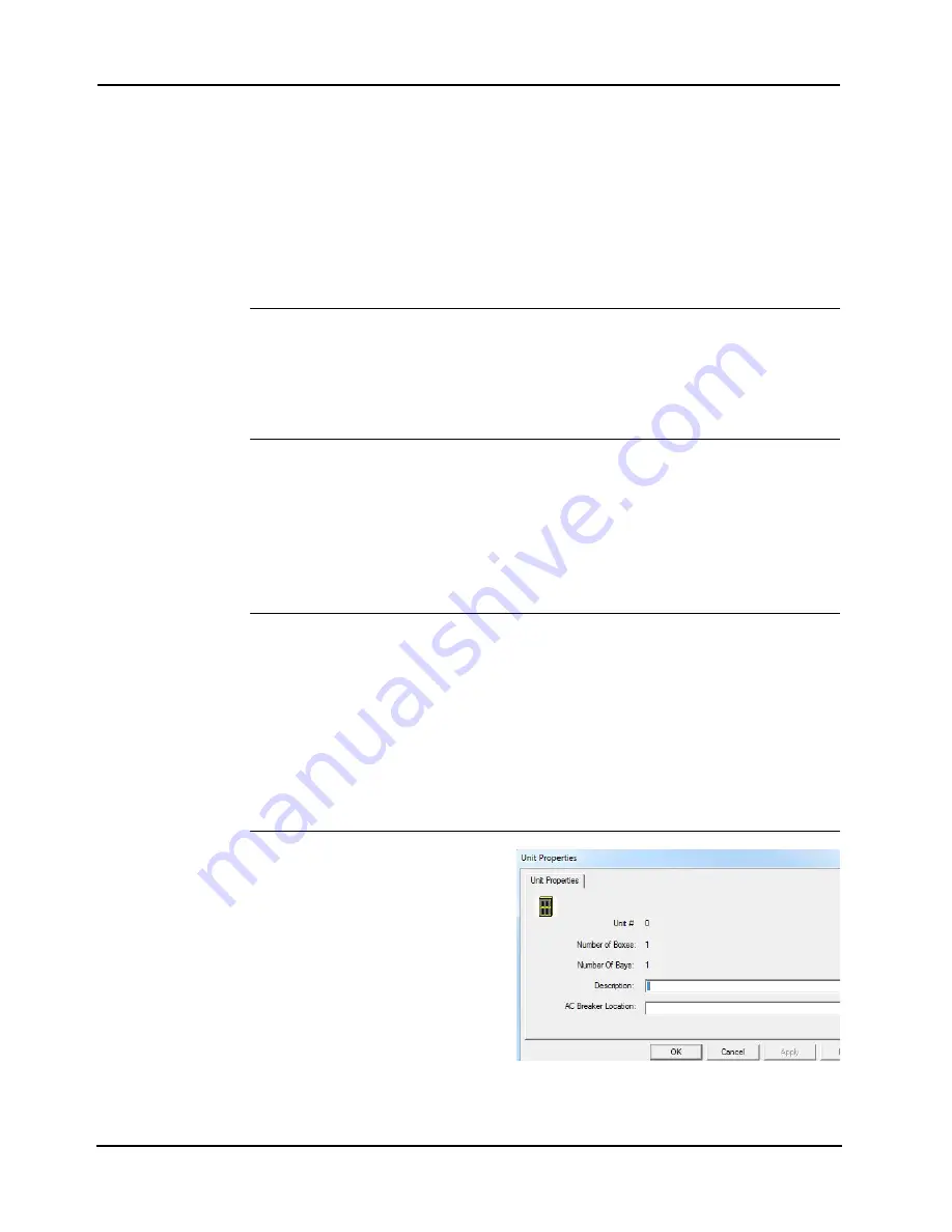
Editing Properties
To access the Properties dialog, right
click on a Unit icon in the work area and
then click on
Properties.
For more
information on the cards and modules’
Properties window, refer to Chapter 6.
For the Box Properties window, refer to
Figure 5-1.
• Description: Enter descriptive text
for the unit.
• AC Breaker Location: Enter the
location of the breaker to which the
power supplies within the unit's boxes
connect.
Figure 5-1. Box Properties Window
Summary of Contents for 4007ES Panels
Page 1: ...4007ES and 4007ES Hybrid Fire Alarm Systems Programmer s Manual 579 1167 Rev D...
Page 2: ......
Page 4: ......
Page 10: ......
Page 18: ......
Page 36: ......
Page 56: ......
Page 122: ...9 38...
Page 132: ......
Page 134: ......
Page 150: ......
Page 166: ...A 16...
Page 167: ......


