Sime SOLIDA 5 Manual Download Page 6

6

not be less than 0.5 bar.

Features of the feed water

The system water must be treated in accord-
ance with BS7593.
The inhibitor concentration must be checked 
frequently particularly in the following cir-
cumstances.
–  Large systems ( high water contents)
–  Frequent replenishments due to system 

leakages.

–  If the system is drained.

BRAZIER GRID ASSEMBLY 

1.2.4 
 (OPTIONAL)

In order to carry out the assembly proceed in 
the following way (fig. 3): 
–  Carefully break out the cast as shown in 

A (fig. 3). Then using a bit of 10 mm as 
indicated in the detail (B).

–  Place the back grid (12) in the combustion 

chamber. 

–  Place the front grid (10) and block it to the 

hub (9) with the screws (8) and the nuts 
(7); block the front grid from the right side 
of the boiler body with the screws (5).

–  Hook the tie rod (6) to the seats extracted 

from the front and rear grid. 

–  Place the intermediate grids (11). 
–  Introduce the ring (4) and the lever (3) on 

the hub (9), fixing then everything with the 
washer (2) and the screw (1).
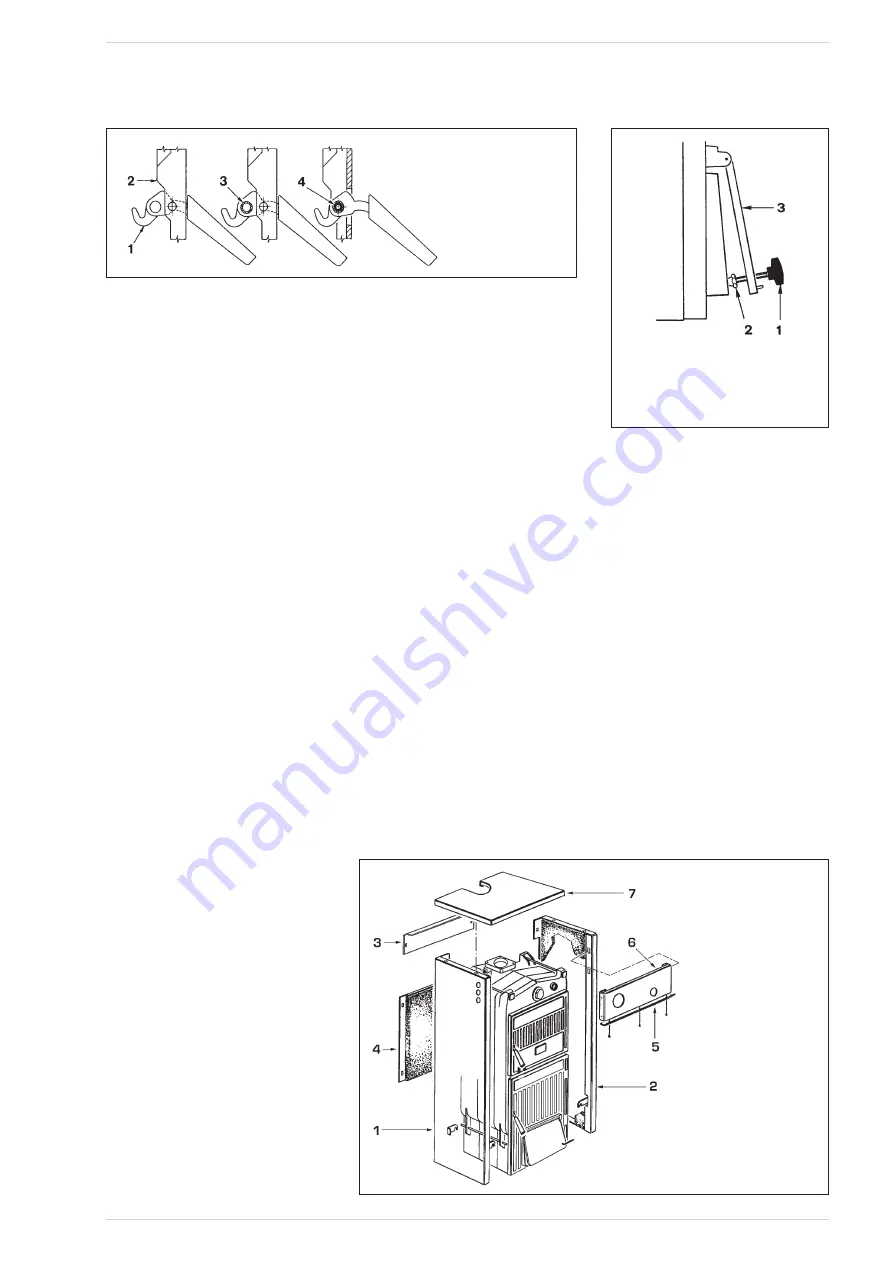
ASSEMBLY OF THE  

1.2.5 

ACCESSORIES

The closing handles for the ports and the 
screw with the adjustment knob for the blast 
gate damper are supplied separately, to avoid  
damaged during the transport. 
Both the handles and the screws with knob 
are packed in a nylon bag, placed inside the 
ash collection basin.
For the assembly of the handles proceed as 
following (fig. 4): 
–  Take a handle (1), insert it in the opening 

of the load port (2) and insert the roller (3) 
in the opening of the handle; secure the 
handle with split pin (4). 

–  Carry out the same operation for the han-

dle of the ash box port. 

To assemble the screw with the knob, pro-
ceed as follows (fig. 5):
–  Remove the screw M8 x 60, which fixes 

the air blast damper to the ash box port 
and screw the screw with the bakelite 
knob (1) on, which is supplied in the pack-
aging.

  Place the blind nut with cap (2) at the end 

of screw M 10. 

–  Fix lever M6 to the air blast damper (3) 

placing it in a horizontal direction on the 
right. The lever has an opening at its end, 
where the chainlet of the thermostatic reg-
ulator will be connected.

CASING ASSEMBLY

1.2.6 

Assemble the casing as shown in figure 6.
The side panes are secured with brackets 
to the tie rods that hold the cast sections 
together: 
–  Loosen the second or third nut of each tie 

rod. 

–  Hook the left side (1) on the lower tie rod 

and superior of the boiler and adjust the 
positposition the nut and locknut to cor-
rectly locate the side panel. 

–  Fit the RHS (2) panel in the same way as 

LHS (1). 

–  Hook the front upper board (3) on to the 

two splines in the opening, on each side. 

–  Carry out the same operation to fix the 

back lower board (4).

–  The protection deflector (5) is fixed to the 

control board (6) with three self-threading 
screws. 

  Fix the board by means of the press fit-

tings. 

  Then uncoil the capillary of the thermom-

eter and place it in the left pocket in the 
rear section of the heat exchanger and 
secure with the clip. 

  The right pocket is used for a temperature 

gauge. 

–  Fix the cover (7).

NOTE: Remove the test certificates and 
boiler documentation from the combus-
tion chamber and keep safe.

DRAUGHT REGULATOR

1.2.7 

The boilers

 SOLIDA 

can be supplied with 2 

types of thermostatic regulators.

NOTE:  In order to fix the lever with the 
chainlet in the regulator holder it is nec-
essary to remove the deflector, which is 
assembled on the control board, by unscrew-
ing the three screws that fix it (fig. 6). 
Replace the protection deflector after the 
assembling and related adjustment.

LEGEND 
1   Handle 
2   Load port 
3   Roll 
4   Elastic split pin


Fig. 4 

LEGEND 
1   Screw with knob M10 x 70 
2   Blind nut with cap 
3   Blast gate damper 

C<><E;Û
~ÛÛ C]^lÛka\]Û
ÛÛ Ia_`lÛka\]Û
€ÛÛ Ggkl]jagjÛkmh]jagjÛZgYj\Û
ÛÛ Ggkl]jagjÛaf^]jagjÛZgYj\Û
‚ÛÛ Gjgl][lagfÛ\]^d][lgjÛ
ƒÛÛ :gfljgdÛZgYj\Û
„ÛÛ :gn]j


Fig. 5 


Fig. 6 

Summary of Contents for SOLIDA 5

Page 1: ...IEB 7 IEB 7 IEB 7 FB IEB 7 FB KA...

Page 2: ...9D8JB CI G A 6H KZg 9ZhXg ei dc Lg iZg 9ViZ...

Page 3: ...af_ kqkl ek 9J I imaj e flk gj d lja Yd afklYddYlagfk oajaf_ j _mdYlagfk Pellets G dd lk k gmd gehdq oal gehdq oal E Ehdmk 8 Safe Handling K afklYddYlagf oadd j imaj log gj egj gh jYlan k lg egn al af...

Page 4: ...ob for the manual adjustment of the blast gate damper a con tact spring for the bulb of the thermometer and the M6 lever to be fixed at the blast gate damper Test certificate to be kept with the docum...

Page 5: ...ated in a position free from down draughts at least 1 metre above the point of exit through the roof or 600mm above the apex of then roof see fig 2a The flue diameter should not be less than the diame...

Page 6: ...1 on which is supplied in the pack aging Place the blind nut with cap 2 at the end of screw M 10 Fix lever M6 to the air blast damper 3 placing it in a horizontal direction on the right The lever has...

Page 7: ...adjustment of the Thermomat which essentially consists in the determina tion of the chainlet length proceed in the following way Place the knob at 60 C Switch on the boiler with opened air gate dampe...

Page 8: ...l p_ Yf_ j MAINTENANCE 1 3 3 fkmj l Yl l Zgad j ak gd Z gj h j gjeaf_ Yfq eYafl fYf gj j hYaj g fgl ehlq l Zgad j o ad l kqkl e water is hot WARNING Only suitably qualified personnel are per mitted to...

Page 9: ...iance The boiler complies with Class 3 in accord ance with EN 303 5 OPERATION WITH PELLETS AND SPECIAL KIT 2 2 1 1 OVERALL DIMENSIONS Fig 12 2 1 2 TECHNICAL FEATURES Model SOLIDA 5 PL SOLIDA 8 PL Nomi...

Page 10: ...the door and remove the latch and screws securing the grill remove the grill A Remove the blind plate Fig 13 Remove the grille Fig 14 Place the cast iron deflector with the rear side supports B 1 Fig...

Page 11: ...RNING THE CEMENT BRICKS MUST BE POSITIONED TO THE FRONT PART OF THE BOILER Place the last cast iron deflector E 3 Fig 21 rd deflector Screw the M10 screws to the blind plate F Fix the plate to the com...

Page 12: ...ut I Burner assembly Fig 25 Fixing of the burner Fig 26 WARNING TIGHTEN THE NUTS UNTIL THE BURNER PLATE RESTS ON THE BOILER PLATE DO NOT OVERTIGHTEN Unscrew the thermostatic regulator if provided and...

Page 13: ...anel hole L Remove the thermometer Fig 29 Plug the hole Fig 30 Block the suction door if the boiler was previously used for operation with wood or carbon M Suction door Fig 31 WARNING OPEN THE LOADING...

Page 14: ...is formed from the packaging N 6 4 5 1 2 2 7 3 4 8 Pos Description No 1 screw feeder tube 1 2 M8 nut 10 3 screw feeder ring 1 4 M8 washer 14 5 M8x20 bolt 6 6 tank 1 7 tank base 2 8 M8x30 bolt 4 Tank...

Page 15: ...er to the safety thermostat B Screw feeder motor cable Fig 33 Safety thermostat connector Fig 34 Pass the NTC sensor through the grommet on the boiler body C NTC sensor cable route Fig 35 Position and...

Page 16: ...3 WAY DIVERTER VALVE HYDRO ALARM LIGHT WARNING LIGHT ALARM SIREN OPTIONAL FLOW SWITCH PLATE HEAT EXCHANGER SANITARY THERMOSTAT CHAMBER PELLET LOADER VENTILATOR IGNITION COIL L N E 230V 50Hz Electrical...

Page 17: ...JE JG HI LIMIT 2 NTC SENSOR positioned in the RHS pocket in boiler body SAFETY THERMOSTAT CR remote push button AT CONNECTION OPTION an ambient thermostat AT a remote control ON OFF push button CR SEC...

Page 18: ...PL RLG97 0042 A16 30252LH 502 ahs 220 240V AC 50 HZ 38W 3 Brazier 4 Pellet grille can be removed for cleaning 5 Photoresistor see the brightness of the flame 6 Pellet feed hole 7 Pellet safety thermos...

Page 19: ...ner may indicate a high ash deposit Once the normal operating conditions are restored the thermosticker returns to its normal colour black The burner thermosticker must be checked on a regular basis a...

Page 20: ...der Loading aperture Screw feeder motor Flexible connection tube BOILER AND PELLET CONTAINER ASSEMBLY 2 4 6 Fig 45 Screw feeder Burner Self extinguishing flexible tube SOLIDA PL boiler Control panel P...

Page 21: ...e 1 wood pellets The automatic pellet burner is designed to use wood pellets with the properties described in the ENplus reference standard Pellet category Ad DU A Ad 0 6 DU 97 0 AB Ad 0 6 DU 97 0 B 0...

Page 22: ...nt ENplus A1 ENplus A2 aYe l j mm C f_l mm C C fkalq c_ e Ydgja a nYdm DA c_ mea alq mkl D Yfa Yd j kaklYf 8k j ka m 8k e dlaf_ l eh jYlmj dgjaf Jmdh mj Ealjg_ f ghh j e_ c_ jgeame e_ c_ 8jk fa e_ c_...

Page 23: ...mllgf oal l gjj khgf af_ F a gf Yf o al aj d c qk o gk mf lagf k jahlagfk Yhh Yj gf l akhdYq dgk lg Y g l e POWERING UP THE SYSTEM 3 3 PANEL STARTUP AFTER CONTROLLED HEATER TYPE SETTING 3 3 1 The disp...

Page 24: ...onditions active Alarms Displayed strings in the START screen Table 4 This notification is only displayed if the ECO option is on and no OFF command has been issued by the user or an ON command has be...

Page 25: ...holding the key pressed for 2s the selection screen will appear See Fig 51 from within this screen the value may be changed by1 level steps within an interval ranging from 1 to the maximum value whic...

Page 26: ...he various functions are listed in the same order as they appear on the display along with their values Function Value Water Temp See 2 5 4 1 Day and Time See 2 5 4 2 Chrono See 2 5 4 3 Settings See 2...

Page 27: ...d to set active the chrono operation mode on the basis of the currently defined weekly on off time pattern when active the relevant string is displayed in the START screen as described in Table 4 The...

Page 28: ...llows the user to set the time and the backlighting level used in the START screen Choosing On the display will then be kept lit up all the time the other items set the time when the backlighting is d...

Page 29: ...shows a screen similar to that used for filling the auger feeder with pellet See Fig 53 Pellet feeder filling function By pressing esc key 1 the display reverts back to the previous screen while the k...

Page 30: ...Airflow at Max Power 0 400 lpm RPM Min Power 300 2750 rpm RPM Max Power 300 2750 rpm Motor Type 0 3 Second Extractor Menu Enable On Off Ignition 1 0 30 Ignition 2 0 30 Shut down 1 0 30 Shut down 2 0...

Page 31: ...rrows or may also change in depending on the displayed data type and they are used to increase or decrease the item value By pressing the button Ok key 3 the new value is confirmed and the display rev...

Page 32: ...hours Service Time 0000 9999 hours Service phone number Fumes Extractor exhauster fan 0000 2500 rpm Fumes Temperature 000 300 C Pellet Feeder Time 0 1 12 0 seconds Water pressure 0 0 5 0 bar User Info...

Page 33: ...us cannot be changed before issuing an unblock command i n f o 8 C 8 I D 8 g n i t i o n a i l e d ALARM screen Fig 57 On the bottom line the alarm type and name is scrolled and in the middle of the t...

Page 34: ...reset them Code Alarm type Informations A01 Ignition Failed Clean Brazier and Restart A02 Flame Shut Down Fill Pellet Tank A03 Pellet Tank Over Temperature See instruction manual A04 Fumes Over Temper...

Page 35: ...ys it is necessary to empty the 80 kg pellet container in order to prevent the pellets from absorbing excessive humid ity which could affect the operation of the boiler A high amount of humidity in th...

Page 36: ...gh jYl l ak Zgad j af Y gj Yf oal l eYfm Y lmj j k afkljm lagfk K _mYjYfl oadd fgl Yhhdq a l Zgad j ak gh jYl gf h dd lk gl j l Yf l gk k jaZ af k lagf K _mYjYfl ak fgl ljYfk jYZd mfd kk Y_j Zq Jae dl...

Page 37: ...37 DEJ I...

Page 38: ...38 DEJ I...

Page 39: ......

Page 40: ...IZX c XVa 9dXjbZciVi dc 9ZeVgibZci I_c BjZ V 7ajZ G Y Z EVg I jcYZg ZVY G Y Z aVhh dj idc 8VhiaZ dgY L J6 E dcZ Vm lll h bZ Xd j Zcfj g Zh h bZ Xd j...

Reviews: