20
is set-up for NATURAL GAS; with the con-
nector
linked-on
, the boiler is ready for
LPG.
–
“ANN. RIT.” connector
(5 fig. 17)
In the heating phase, the electronic board
is programmed to include a burner tech-
nical delay interval of approx. 90 seconds,
which occurs both at system cold star-
ting and at subsequent re-ignitions. The
aim is to overcome the problem of repea-
ted ignitions and turning off with very
short time intervals between. This could
occur in particular in systems presenting
high head losses.
At each restart after the period of slow
ignition, the boiler will set itself for about
1 minute at the minimum modulation
pressure, and will then move to the hea-
ting pressure value set.
When the connecting link is inserted,
both the programmed technical pause
and the period of operation at minimum
pressure in the startup phase will be can-
celled. In this case, the times elapsing
between turning off and subsequent re-
ignition will depend on a temperature dif-
ference of 5°C detected by the SM sen-
sor (heating flow sensor).
–
DIP SWITCH
(13 fig. 17)
Check that the switches are positioned
as shown.
Flashing red led,
communication fault
with “Logica Remote Control”
Green led off if
power is cut-off
Flashing red led, water
pressure is too low (*)
Flashing red led, heating sensor fault (SM)
Flashing red led,
plant safety
valve tripped (*)
Red led on, ignition blocked:
rotate selector CR/OFF/SUM/WIN/RESET
to release position (
)
to restore operation
Flashing red led, safety/smoke stat tripped.
Rotate selector CR/OFF/SUM/WIN/RESET
to release position (
)
to restore operation
Flashing red led, fan fault.
30 minutes after the fan has switched off,
the board will attempt a restart
(*) When all 0.5 to 2.5 bar leds are off, check the water
pressure transducer connection.
WARNING: the operation of plants with open vessels is
guaranteed only for static pressures above 0.7 bar.
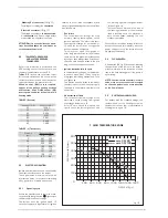
Fig. 16
Flashing red led, flame detection circuit fault
15
13
1
3
5
7
8
9
10
11
12
14
6
6
10
KEY
1 Ignition electrode earth faston
3 Fuse (1,6 AT)
5 “ANN. RIT.” connector
6 “POT. ACC.” trimmer
7 Conector “MET-GPL”
8 D.H.W. potentiometer
9 Ionisation electrode faston
10 “POT. RISC.” trimmer
11 C.H. potentiometer
12 Selector CR/OFF/SUM/WIN/RESET
13 DIP SWITCH
14 Connector “Modureg Sel.”
15 Connector “Albatros”
NOTE: To gain access to trimmers (6) and (10), unscrew the central hea-
ting potentiometer knob
Fig. 17
Flashing red led, flowmeter fault


