SIM18 EVB kit User Guide
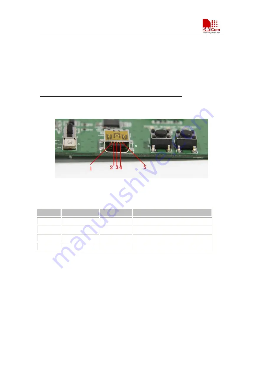
3.2.1 USB Interface
There is one Mini-USB interface on SIM18-EVB, which is transferred to UART by a USB to
UART chip CP2103 on the EVB board. User need to install CP2103 driver in their PC first, then
connect the EVB board to the PC by a USB cable, and set S301 switch be VBUS to power the
SIM18-EVB.
Please download the latest CP2103 driver according to the PC’s OS from the following link:
http://www.silabs.com/products/mcu/pages/usbtouartbridgevcpdrivers.aspx
Or contact SIMCom support for it.
Figure 4: USB interface
Table 3: USB pin definition
Pin
Signal
I/O
Description
1 VBUS
I 5V
input
2 D- IO
Data
minus
3 D+ IO
Data
plus
4
、
5 GND
GND
3.2.2 RF Interface
The RF connector is connected to the active GPS antenna for GPS demonstration.
Note: When the RF connector is connected to a passive antenna, S302 switch must be
unsoldered.
SIM18_EVB kit_User Guide_V1.01
2010.11.16
10


