background image


 ENGLISH 

1.  GENERAL INFORMATION 


WARNING: Please read and understand perfectly the present instruction before using the machine. 
 

SIMA S.A. thanks you for your trust in our products and for purchasing the BENDING OR COMBINED 

ELECTRICAL CUTTING/BENDING MACHINE. 


This manual provides you with the necessary instructions to start, use, maintain and in your case, repair of 

the present machine. All aspects as far as the safety and health of the users is concerned have been stated. 


Respecting all instructions and recommendations guarantees safety and low maintenance.  


As such, reading this manual carefully is compulsory for any person responsible for the use, maintenance or repair of 

this machine. 


It is recommended to have always this manual in an easily accessible place where the machine is being 


2.


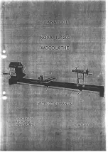
GENERAL DESCRIPTION OF THE MACHINE 


• 

The STAR 20 bending machines have been manufactured to bend flat and reinforced steel bars used for 

construction and passive steel armatures for structural concrete. The bending operation is done in cold using 

mandrels to guarantee the bending interior diameter is conforming to the European norms. 


• 

The combined machines bending/cutting models COMBI are designed to bend as well as cut steel bars. The 

cutting tools are two blades, one fixed and one moving. The cutting operation is done manually by pushing 

the bar on the roller, dropping the bar into the cutting throat, lowering the protection guard and pressing the 

pedal. 


Any other use of this machine is considered inadequate and can be dangerous. Thus, this is completely 
prohibited. 


• The gear box is the main element of the machine. It is responsible for transmitting the needed energy to carry 

out the steel bars bending. 


• The machine is operated by an electrical motor that passes the movement, by a transmission to the bending 

mechanism in which the different mandrills are mounted. 


• The bending plate can be selected to work in two different directions, left or right, by changing the direction of 

rotation in the electrical control panel. 


• The bending angle can be decided by inserting the pivot in the bending plate. For a more precise bending, the 

ruler can be accurately adjusted by its handle. 


• The commands panel is endowed with polyester, electrical knobs easily identified by pictograms. 


• The machine is equipped with shutdown and backward movement buttons to facilitate its manoeuvre. The 

emergency knobs on both sides of the machine can be used in case of danger or incorrect manoeuvres. 


• The general bars bending manoeuvre is performed in low-voltage (24V) according to the European standards. 


• The original equipment (bolts, mandrels bending square) are heat-treated to withstand the tough type of work 

the machine performs. 


• The machine is furnished with a pedal to confirm and execute the manoeuvre, thus avoiding the upper parts to 

be trapped while the machine is running. 


• The work area is protected by a safety guard to limit possible accidents. This guard is transparent to allow 

observation of the material being bent, avoiding getting to the upper parts of the bending area. 


• The machine is painted in oven with a highly resistance, anti-corrosion epoxy polyester paint. 
 

• The original, electrical equipment is in conformity with the EC safety norms. 


Any use of the machine for applications other than those stated above is dangerous and therefore 

strictly prohibited. 


Summary of Contents for STAR-20

Page 1: ...ENDING ANGLE 9 7 GETTING STARTED 10 7 1 CONNECTING TO THE SUPPLY 10 7 2 CONNECTING TO ELECTRICITY SOURCE 11 7 3 CIRCUIT DIAGRAMS 12 7 4 CHANGING PHASES TO ESTABLISH CORRECT BENDING DIRECTION 15 8 MAKING A BEND 16 9 MAINTENANCE 18 10 TROUBLE SHOOTING 19 11 DATA SHEET 19 12 BENDING CAPACITY 19 13 SAFETY RECOMMENDATIONS 20 14 WARRANTY 21 15 SPARE PARTS 21 16 ENVIRONMENT PROTECTION 21 17 DECALARATIONS...

Page 2: ...ar box is the main element of the machine It is responsible for transmitting the needed energy to carry out the steel bars bending The machine is operated by an electrical motor that passes the movement by a transmission to the bending mechanism in which the different mandrills are mounted The bending plate can be selected to work in two different directions left or right by changing the direction...

Page 3: ... FORCE RETURN SWITCH 4 ON LIGHT 5 VOLTOMETER 6 AMPERE METER 7 EMERGENCY STOP BUTTON 1 BAR SUPPORT 2 BENDING BLADE PROTECTION 3 BAR LENGTH MEASURER 4 PRECISION ANGLE ADJUST 5 CHASIS 6 BENDING SUPPORT 7 END OF BEND SENSOR 8 BENDING MANDRELS 9 BENDING PLATE 10 END OF BEND SENSOR 11 12 PEDAL ...

Page 4: ...y of use and the nature of the load The choice is correct if special norms of use are respected Fig A WARNING To avoid any possible danger stay away from elevated loads and be careful with their possible displacement during transport whether during lifting or mooring Therefore it is essential to choose the correct slings and remain particularly vigilant in sensitive operations elevation coupling m...

Page 5: ...h the accessories uninstalled Install the accessories as in the pictures BENDING PLATE PROTECTION This needs to be mounted for the machine to work The protection presses a micro switch which needs to be pressed for the machine to work correctly BAR SUPPORT This is for convenience and speed of productivity ...

Page 6: ...or the bend The bending support can be mounted on the right or left side To reposition the bending support loosen the screw and slide the support along 6 2 PARTS OF THE BENDING PLATE The plate has many holes for different purposes 1 Holes for pushing mandrel Depending on the size of bar the mandrel can be put in different positions 2 Screw holes for extracting the bending plate 3 Micro plate for s...

Page 7: ...nding angle of the plate Depending on if the plate is moving clockwise or counter clockwise we have to put the pin on the left or the right of S2 Sensor S2 it to stop the plate turning when the inversion pin P touches it Sensor S1 is for stopping the plate when it returns to it s original position S1 ...

Page 8: ...n cable used to feed the machine needs to have a minimum section of 4x2 5 mm 2 up to 25 meters long For a superior distance 4x4 mm2 can be used In one of its ends it is needed to connect a base normalized aerial of 3P T or 3P N T compatible with the machine switch and in the other end one normalized aerial pin of 3P T ó 3P N T compatible with switchboard exit Machines with electrical motor should ...

Page 9: ...pedal to check which way the plate is turning MAKE SURE THERE ARE NO MANDRELS OR ACCESSORIES ON TOP OF THE MACHINE Do not change any electrical configuration in the machine as this may result in irreparable damage When connecting the machine make sure the machine is turning in the way the sticker indicates this will avoid accidents with the accessories on the bending plate If it doesn t turn the r...

Page 10: ...12 ENGLISH 7 3 CIRCUIT DIAGRAMS ...

Page 11: ...13 ENGLISH ...

Page 12: ...14 ENGLISH ...

Page 13: ...the process press the RETURN button and use the pedal to return to a previous position or to the start 7 4 CHANGING PHASES TO ESTABLISH CORRECT BENDING DIRECTION To change the direction of the bend you will have to open the connecting socket and interchange the wires as shown in the image ...

Page 14: ... 5 To make the plate return lift your foot off the pedal and press again and the plate will return If you haven t achieved the bending angle you require with the pin and you need to make a small adjustment you can use the black metal handles on the side of the machine to move the support mandrels Turn the handle to push the mandrel further away to make a tighter angle and bring it towards to make ...

Page 15: ...17 ENGLISH ...

Page 16: ...ns and mandrels go and also the bottom of the pins and mandrels this will also help avoid build up of rust 3 At the end of the day disconnect the machine 4 Cover the machine at night to protect from rain 5 When possible remove debris form the inside of the machine 6 Clean the exterior and grease pins and mandrels frequently 7 Check the blades on the cutter every 8 days of use to see if they need c...

Page 17: ...ght doesn t switch on Check cables to the machine check supply Check cables to the machine check supply Pilot light is on but machine doesn t work Machine is not well connected Machine is only connected in a single phase make sure it is correctly connected Connection is correct at 230 or 400 but the machine isn t moving Unstable supply Check the supply try to use a stabiliser 11 DATA SHEET 12 BEND...

Page 18: ...he safety guards in their correct positions Attention Before placing the bolts mandrills and the bending squares check the direction of rotation of the bending plate You can then install the suitable accessories for the type of work you want to make The damaged electrical cables should be urgently replaced Unplug the machine from the electricity and never manipulate nor operate on the mechanical n...

Page 19: ...nd in the spare parts plan attached to this manual To order any spare part please contact our alter sales service clearly indicating the serial number of the machine model manufacturing number and year of manufacturing that show on the serial number plaque or sticker 16 ENVIRONMENT PROTECTION Raw materials have to be collected instead of throwing away residuals Instruments accessories fluids and p...

Page 20: ...22 ENGLISH ...

Reviews: