


9
The video signals applicable to this input can have scanning
frequencies of 15 kHz (standard resolution video), 32 kHz or
higher (progressive scanning video and high definition video).
Sometimes it is possible to choose whether to obtain a
progressive instead of interlaced signal from the source.
Although, in general a progressive signal provides better quality
than an interlaced signal, it is often preferable not to perform the
de-interlacing operation on the source but on the RTX system,
which is equipped with sophisticated DCDi™ technology from
Faroudja specifically for this purpose.
Even if as a rule progressive signals provide better quality than
interlaced signals, for sources offering both outputs, it is advisable
to compare the quality of the two images reproduced by the
RTX system in the two cases: the de-interlacing performed by
the RTX system (thanks to Faroudja’s DCDi™ technology) is
often more effective than that performed at the source (typically
DVD players).
RGB GRAPHICS
Apply an RGB-type video or graphic signal to this input, using a
cable with a DB15HD-type connector.
The device providing the signal (typically a personal computer
or videogame console) must be able to provide separate H/V
synchronisms or composite synchronisms on the green signal
(RGsB).
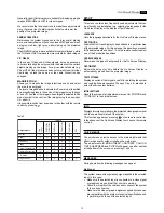
The video or graphic signals applicable to this input can have
horizontal scanning frequencies (H-sync) between 15 and 110
kHz and a vertical frequency (V-sync) between 40 and 100 Hz.
Image resolution can vary between 640x480 and 1600x1200
pixels (VGA, SVGA, XGA, SXGA, UXGA).
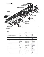
3
1
2
3
3
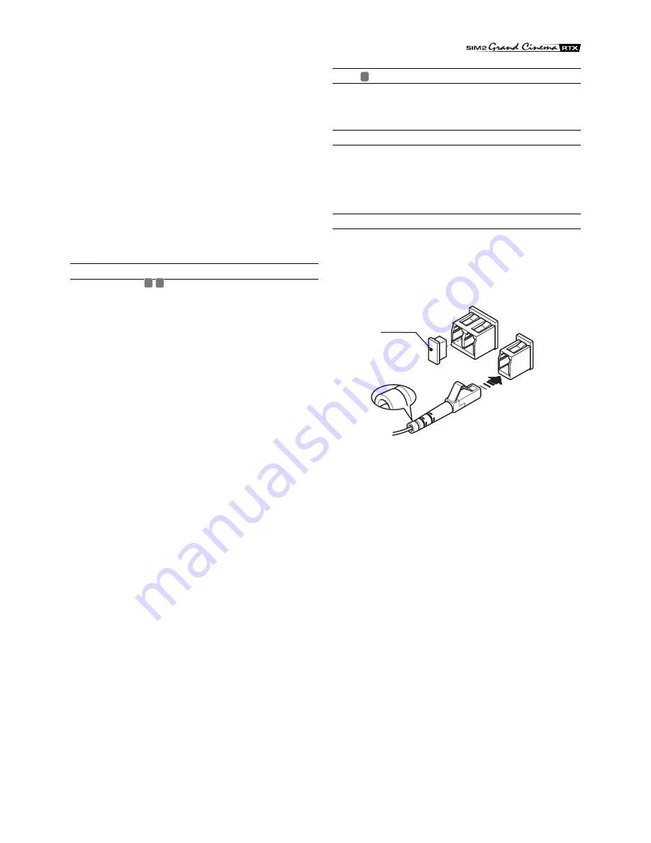
Protection
plug
Fig. 5
DVI-D
If your source is equipped with it (more and more computers
now have it) you can take advantage of the better image quality
by using the DVI-D input.
CONTROL (RS232)
It is possible to control the system with a personal computer or
domestic automation device through the serial port: all you need
to do is connect a cable coming from an RS232 serial port. Ask
SIM2 for the document containing the serial port settings and
the list of main commands.
OPTICAL FIBRE LINK
After removing the protection plugs present on the fibre
connectors and the panel connectors, carefully insert the fibres
in their respective connectors, matching the numbers shown on
each element. Be very carefully when handling the fibres and
connectors.
9 10
11


