


User Guide (Version 2.2) of the
SiRad Simple® Evaluation Kit
- 10 -
2.2.2 Connecting to the Board via USB
If you want to connect to the sensor via WiFi instead of USB, please directly continue with
Section 2.2.3. The sensor board can be connected to a PC via USB through an FTDI cable
(delivered with the evaluation kit), which provides a virtual COM port. We recommend using a cable
with FTDI chipset instead of cheaper alternatives since a lot of our customers found the cheaper
alternatives to be very unstable. If you want to use a cheaper alternative, skip the next point and
see the vendor’s website of your cable.
Installing the FTDI driver
Microsoft Windows usually installs the driver automatically once the FTDI cable is connected to the
PC. Therefore, the PC has to be connected to the internet and the automatic driver installation
feature has to be enabled (default behavior). If you need to install the driver manually, go to the
FTDI Chip website
5
and download the latest VCP driver. Please read the Installation Guide and
Release Note linked on the vendor’s website. Once the FTDI driver is installed, the FTDI cable
connected to the sensor and to the PC should provide a virtual COM port. On Microsoft Windows,
the COM port number can be checked in the device manager by connecting and disconnecting the
USB port of the FTDI cable. Before you proceed with the installation of the software, you can now
optionally connect to this serial port using a terminal program such as PuTTY
6
or Realterm
7
with the
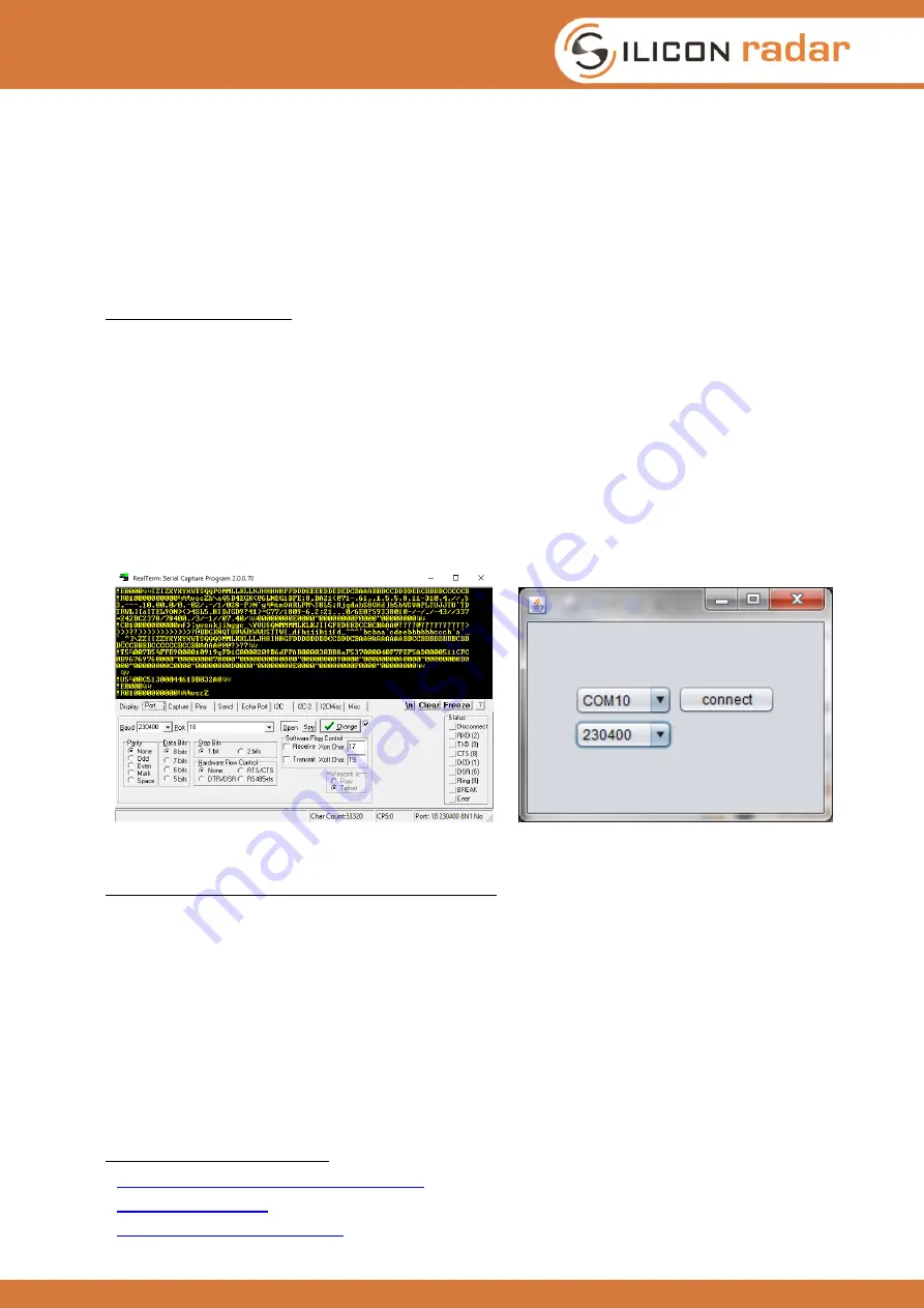
following UART settings: 230400 baud, 8 bits, 1 stop bit, no flow control. You should see plenty of
protocol output from the sensor like in Figure 7 (left).
Figure 7: Terminal output of the sensor (left) and COM2WebSocket tool (right)
Installing the Evaluation Kit’s COM2WebSocket tool
The Evaluation Kit software contains a COM2WebSocket tool that creates a WebSocket from the
virtual COM port to provide it to the graphical user interface. You can find the tool in the Install
Package in the ‘Software’ folder. The COM2WebSocket tool is portable and can be copied to a path
of your choice on your PC. Make sure that the java.exe of your Java JRE or SDK installation is
available in the PATH variable of Windows, then start it by double clicking the Com2Websocket.jar
file. Alternatively, or if you do not have Admin rights, you can also change the path to the ‘java.exe’
file of your Java installation in the file ‘runme.bat’ of the COM2WebSocket tool and then run it by a
double click on the ‘runme.bat’ file. In the COM2WebSocket application window, select the virtual
COM port number that belongs to your sensor board and select 230400 baud as the baudrate like
shown in Figure 7. A click on the ‘connect’ button opens a WebSocket server, which is fed with the
data coming from the sensor board. Proceed to Section 2.2.4 for running the graphical user
interface.
5
http://www.ftdichip.com/Drivers/VCP.htm
6
7