Silicon Radar SiRad Easy Manual Download Page 5


- 5 - 

Evaluation Kit 

SiRad Easy® r4, SiRad Easy® & SiRad Simple® 

User Guide 

Version 2.5 

19-Nov-2021


1.2


Application 

 
SiRad  Easy®  r4,  SiRad  Easy®  and  SiRad  Simple®  are  supposed  to  be  used  for  short-term  evaluation  purposes  in 
laboratory environments. Please see our disclaimer at the end of this document. 
 
IMPORTANT: 
The  radar  front  ends  are  able  to  use  a  larger  bandwidth  than  what  is  allowed  in  the  ISM  bands.  In  most 
countries, the bandwidth is limited to 1 GHz between 122 GHz and 123 GHz for production purposes by law. 
Please check your local regulations. It remains the customer’s responsibility to assure the operation of the front 
end  according  to  local  regulations,  especially  when  applying  to  frequency  band  allocations  outside  of  the 
laboratory environment. Silicon Radar and its distributors will not accept any responsibility for consequences 
resulting from the disregard of these instructions and warnings. 


2


Hardware Setup SiRad Easy® r4 


2.1


Changing the Radar Front End 

 
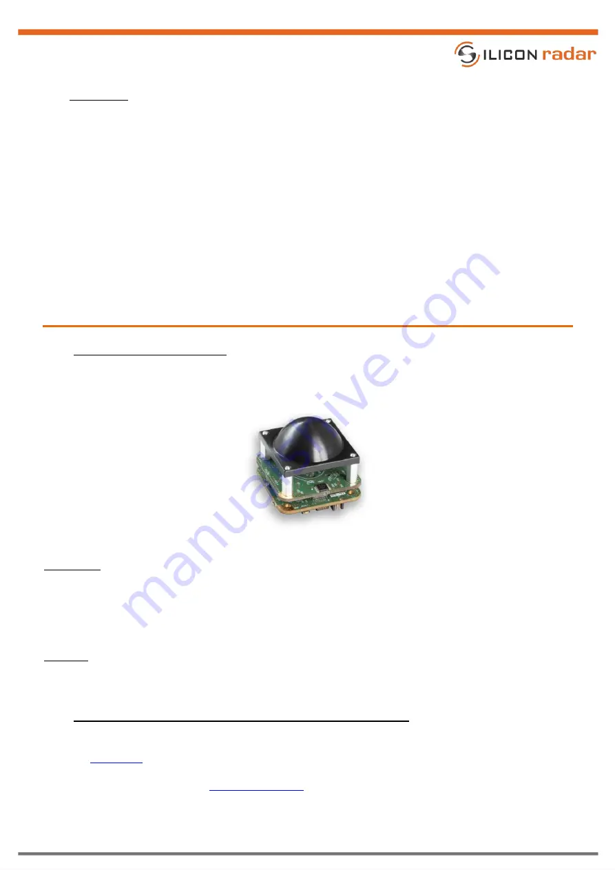
Figure 2 shows SiRad Easy® r4 with a 122 GHz radar front end board mounted. Follow the instructions below for 
changing the front end board. 


Figure 2 

122 GHz configuration with lens assembled 

 
Disassembly 


Disconnect the power from the Evaluation Kit. 


Remove the radar front end from the top of the baseband board. Press thumbs and index fingers under 
the edges of the radar front end board and pull and press it simultaneously straight out of its connections. 
Do not tilt or bend the front end board.  

 
Assembly 


The radar front end board can only be connected one way. Place the radar front end board centered onto 
the connectors, then press it down until no space is left. 


2.2


UART Data Connection & External Power (External UART Header) 

 
The UART header in Figure 3 provides an alternative way to power and connect to the board using a second UART 
port. Th

Base Board

 can be powered from the 5V and GND lines of the port. The UART header can also be used 

to trigger measurements manually via the trigger line (TI), or receive triggers on each ramp start (TO). Also see the 
section about trigger options in the 

Protocol Description

. 

Summary of Contents for SiRad Easy

Page 1: ...uide SiRad Easy Simple Version Product number Package Marking Page 2 5 1 of 14 Document Annex to VA U03 01 Anlage 8 Template Datenblatt RevE Date 19 May 2020 Rev D Silicon Radar GmbH Im Technologiepar...

Page 2: ...SiRad Easy r4 5 2 1 Changing the Radar Front End 5 2 2 UART Data Connection External Power External UART Header 5 2 3 PLL Control Connection External PLL Header 6 2 4 Data Connection External Power B...

Page 3: ...ed 7 Figure 8 External header J1 pinout 7 Figure 9 Hardware configuration for Serial USB connection 8 Figure 10 Hardware configuration for WiFi connection 8 Figure 11 WiFi module update configuration...

Page 4: ...a free graphical user interface WebGUI for user friendly parametrization of the baseband board and multiple visualization modes for radar data Due to the flexibility of the system it can be used to ch...

Page 5: ...anging the Radar Front End Figure 2 shows SiRad Easy r4 with a 122 GHz radar front end board mounted Follow the instructions below for changing the front end board Figure 2 122 GHz configuration with...

Page 6: ...he PLL Mx MUXOUT output line of uC reserved Da DATA line of the PLL Le LE line of the PLL Fs PLL FSK line of uC reserved 1 8V Figure 4 PLL control header pinout 2 4 Data Connection External Power Brea...

Page 7: ...controller board to exchange the front end board Assembly The radar front end can only be connected one way since the connector pins are different Slightly press it down and make sure no pins are bent...

Page 8: ...via the external header pins 5V and any of the four GD pins 3 2 2 Wireless Data Connection In WiFi mode the external header J1 is used to connect the WiFi module to the microcontroller on the board P...

Page 9: ...cable with 3 3V TTL levels Switch SW1 to the PROG position Figure 11 WiFi module update configuration Figure 12 WiFi module select switch SW1 Download esptool Copy the desired firmware into a folder...

Page 10: ...igger options in the Protocol Description Pin Description 5V 5V GD GND MT microcontroller TX MR microcontroller RX TR external trigger line WT WiFi TX WR WiFi RX 3 3V tolerant only Figure 13 External...

Page 11: ...I cable or Serial USB adapter using the external header J1 Please read Section 4 1 about the external header connection Connect line TX to MR microcontroller RX and line RX to MT microcontroller TX Ma...

Page 12: ...WiFi module gets programmed indicated by a flashing blue LED The programming is finished after about 40 seconds Switch the DIP switch WP back to the OFF position and connect a jumper between MT and WR...

Page 13: ...erial UART is available on the external header J1 lines MR and MT SER2 Serial USB is available on the USB port only on SiRad Easy You can connect to both SER1 and or SER2 using a terminal program such...

Page 14: ...l as any common law duties relating to accuracy or lack of negligence with respect to this material any Silicon Radar product and any product documentation Products sold by Silicon Radar are not suita...

Reviews: