


S E N S O R L E S S - B L D C - M O TO R - R D
Rev. 0.3
5
5. HyperTerminal Demonstration
Before connecting the USB cable to your computer, make sure you have installed the Reference Design Kit Tools,
including the Virtual COM port driver by following the instructions in Section “4. Reference Design CD Installation”.
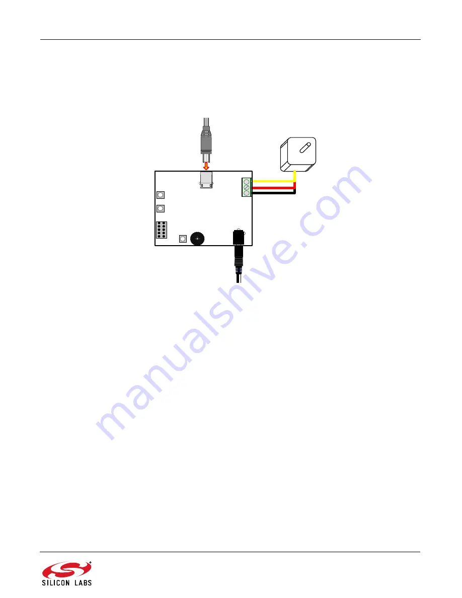
Start with the Demo Setup and add a USB cable connection to your computer as shown in Figure 4. The USB
connection is used with a terminal program to provide a basic terminal interface for the Sensorless BLDC motor.
Figure 4. Sensorless BLDC Motor Reference Design Terminal Setup
Before opening HyperTerminal, you need to determine which COM port is being used for the Sensorless BLDC
Motor drive. Right-click on My Computer and select “Properties” (see Figure 5 on page 6). This will bring up the
System Properties window. Select the Hardware tab and then click on the Device Manager button. This will bring
up the Device Manager. Expand the Ports (COM & LPT) item. You should see the CP210x USB to UART bridge
controller with the COM port number. Use this COM port number when opening HyperTerminal.
Sensorless
BLDC
Motor
Sensorless
BLDC Motor
Drive
SPEED
USB
RESET
DEBUG
STOP
START
AC Adapter
P1
USB Cable


