


ToolStick-F321DC
Rev. 0.1
9
6.5. Enabling and Using Watch Windows
The Debug Windows in the View menu are used to view and modify hardware registers. To view and modify
variables in code, the IDE provides Watch Windows. Just as with register debug windows, variables in the watch
windows are updated each time the device is halted. This section of the User’s Guide explains how to add a
variable to the watch window and modify the variable. In the
F321DC_FeaturesDemo
example code, the variable
Num_LED_Flashes
is a counter that stores the number of times the LED blinks.
1. If the device is running, stop execution using the “
Stop
” button or use the
Debug
→
Stop
menu option.
2. In the File View on the left-hand side of the IDE, double-click on
F321DC_FeaturesDemo.c
to open the source
file.
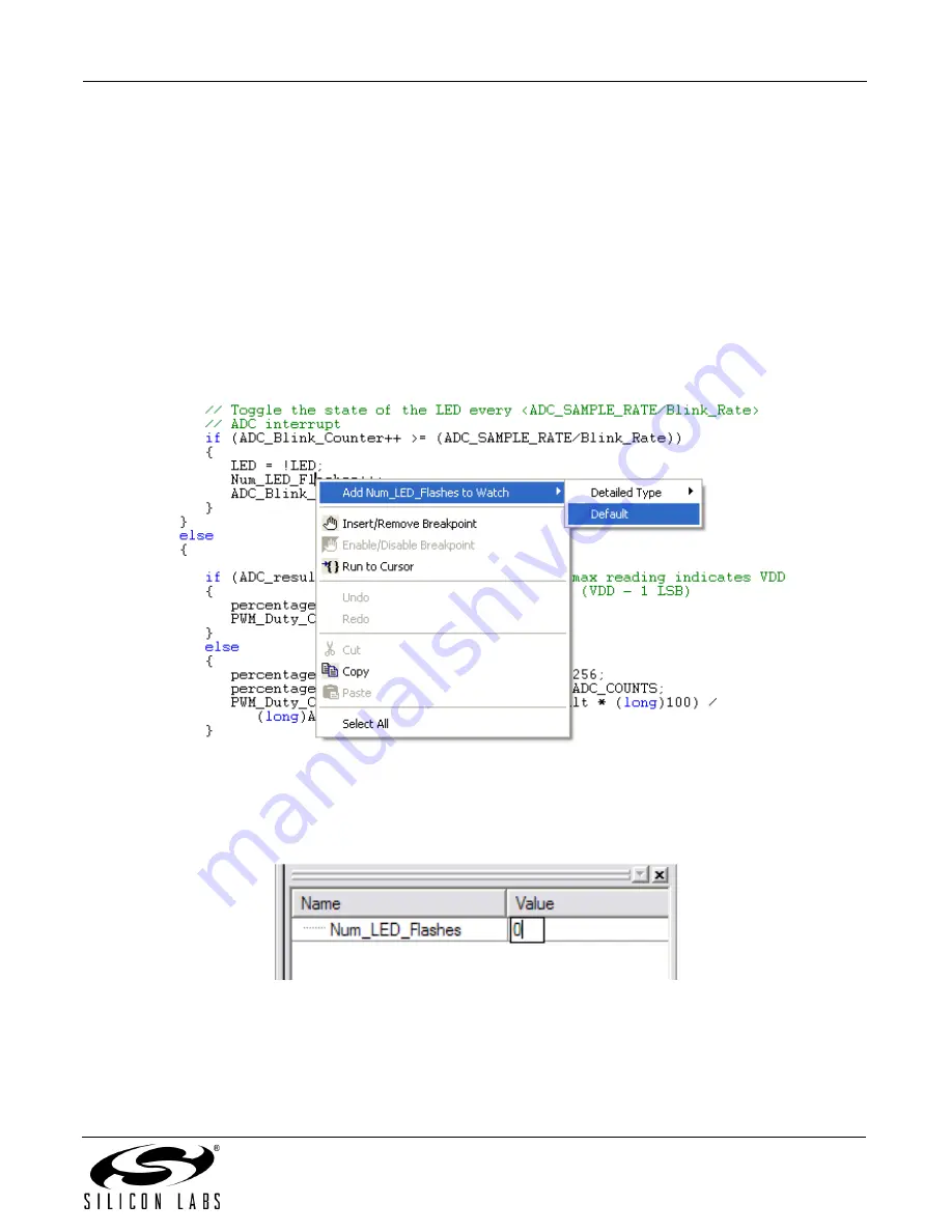
3. Scroll to the
ADC0_ISR
function and right-click on the variable “
Num_LED_Flashes
”. In the context menu that
appears, select “
Add Num_LED_Flashes to Watch
” and then choose “
Default
.” On the right-hand portion of
the IDE, the watch window appears and the variable is added. The current value of the variable is shown to the
right of the name.
4.
Start
and
stop
the device a few times. See that the value of the
Num_LED_Flashes
is incremented each time
the LED blinks.
5. When the device is halted, click on the value field in the watch window and change the value to 0. Then click the
Refresh
button or select
Debug
→
Refresh
to write the new value to the device.
6.
Start
and
stop
the device a few times to watch the variable increment starting at 0.
Changing the values of variables does not require recompiling the code and redownloading the firmware. At any
time, the device can be halted and the values of the variables can be changed. The firmware will continue
execution using the new values.


