


7. RF Performance
7.1 Conducted Power Measurements
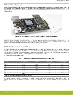
During measurements the BRD4154A Radio Board was attached to a Wireless Starter Kit Mainboard which was supplied by USB. The
voltage supply for the Radio Board was 3.3 V.
7.1.1 Conducted Measurements in the 2.4 GHz band
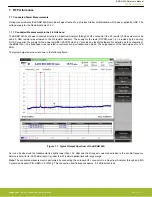
The BRD4154A board was connected directly to a Spectrum Analyzer through its UFL connector (the R1 resistor (0 Ohm) was removed
and a 0 Ohm resistor was soldered to the R2 resistor position). The supply for the radio (RFVDD) was 1.8 V provided by the on-chip
DC-DC converter, the supply for the power amplifier (PAVDD) was 3.3 V provided by the Motherboard (for details, see the schematic of
the BRD4154A). The transceiver was operated in continuous carrier transmission mode. The output power of the radio was set to 19.5
dBm.
The typical output spectrum is shown in the following figure.
Figure 7.1. Typical Output Spectrum of the BRD4154A
As it can be observed the fundamental is slightly lower than 19.5 dBm and the strongest unwanted emission is the double-frequency
harmonic but with its -56.45 dBm level it is under the -37.6 dBm applied limit with large margin.
Note:
The conducted measurement is performed by connecting the on-board UFL connector to a Spectrum Analyzer through an SMA
Conversion Adapter (P/N: HRMJ-U.FLP(40)). This connection itself introduces approx. 0.3 dB insertion loss.
BRD4154A Reference Manual
RF Performance
silabs.com
| Smart. Connected. Energy-friendly.
Rev. 1.0 | 9


