


External Components
007-4653-001
167
Operator’s Panel
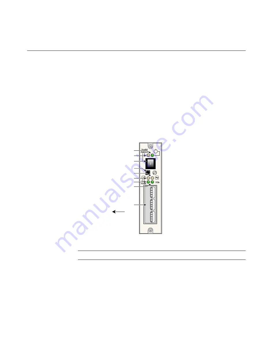
The operator’s panel (ops panel) contains LEDs that show the status of all modules. The
enclosure services processor, located on the LRC modules, control the status LEDs. Also
on the operators panel is an audible alarm that indicates a fault state is present, a
push-button alarm mute switch, and a thumbwheel enclosure ID address range selector
switch. When the D-brick2 is powered on, the audible alarm sounds for one second, and
the power-on LED illuminates.
Figure 11-6 identifies all controls and indicators on the ops panel. Note that the
operator’s panel configuration switches slide left for “on” and right for “off.” For
detailed descriptions of the LEDs and configuration switch information, see Chapter 5 in
the
SGI Total Performance 9100 (2Gb TP9100) Storage System User’s Guide
(P/N
007-4522-00
x
).
Figure 11-6
Operator’s Panel
Note:
The valid range for the address switch is 1 through 6. Zero is not valid.
Invalid address ID LED
Enclosure ID switch
System/ESI fault LED
Hub mode LED
2 Gb/s link speed LED
Configuration switches
Power-on LED
PSU/cooling/temperature fault LED
Alarm mute switch
On
Off
ID
1
2
3
4
5
6
7
8
9
10
11
12
Summary of Contents for Origin 3900
Page 1: ...SGI Origin 3900 Server User s Guide 007 4653 001 ...
Page 3: ...007 4653 001 iii Record of Revision Version Description 001 October 2003 Original Release ...
Page 4: ......
Page 12: ......
Page 18: ......
Page 62: ......
Page 65: ...Product Description 007 4653 001 39 Figure 2 1 512 processor Origin 3900 Server ...
Page 76: ......
Page 104: ......
Page 120: ......
Page 172: ......
Page 198: ......
Page 208: ......
Page 254: ......
Page 274: ......
Page 292: ......