


SECTION 1
GENERAL
The operating instructions mentioned here are partial abstracts
from the Operating Instruction Manual. The page numbers of
the Operating Instruction Manual remain as in the manual.
1-1
4
Getting Started
Warning on power connection
• Use an appropriate power cord for your local power
supply.
Examples of plug types
• Before disconnecting the power cord, wait at least 30
seconds after turning off the power to allow the static
electricity on the CRT display surface to discharge.
• After the power has been turned on, the CRT is
demagnetized (degaussed) for about 3 seconds. This
generates a strong magnetic field around the metal frame,
which may affect the data stored on magnetic tapes and
disks near the bezel. Place magnetic recording equipment,
tapes and disks away from this monitor.
The outlet should be installed near the equipment
and be easily accessible.
Precautions
Installation
• Prevent internal heat build-up by allowing adequate air
circulation. Do not place the monitor on surfaces (rugs,
blankets, etc.) or near materials (curtains, draperies) that
may block the ventilation holes.
• Do not install the monitor near heat sources such as
radiators or air ducts, or in a place subject to direct
sunlight, excessive dust, mechanical vibration or shock.
• Do not place the monitor near equipment which generates
magnetism, such as a transformer or high voltage power
lines.
Maintenance
• Clean the cabinet, panel and controls with a soft cloth
lightly moistened with a mild detergent solution. Do not
use any type of abrasive pad, scouring powder or solvent,
such as alcohol or benzine.
• Do not rub, touch, or tap the surface of the screen with
sharp or abrasive items such as a ballpoint pen or
screwdriver. This type of contact may result in a scratched
picture tube.
• Clean the screen with a soft cloth. If you use a glass
cleaning liquid, do not use any type of cleaner
containing an anti-static solution or similar additive as
this may scratch the screen’s coating.
Transportation
When you transport this monitor for repair or shipment, use
the original carton and packing materials.
Use of the Tilt-Swivel
With the tilt-swivel, this monitor can be adjusted to the
desired angle within 180° horizontally and 20° vertically.
To turn the monitor vertically and horizontally, hold it at
the bottom with both hands as illustrated below.
for 100 to 120 V AC
for 200 to 240 V AC
Getting Started
90
°
90
°
15
°
5
°
for 240 V AC only
5
Getting Started
Getting Started
F
GB
ES
C
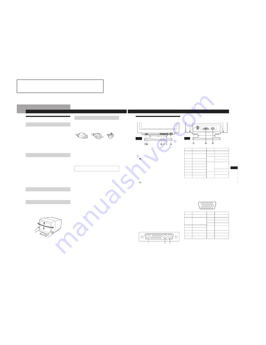
Identifying Parts and Controls
Front
See the pages in parentheses for further details.
1
?
(reset) button (page 16)
Resets the adjustments to the factory settings.
2
(auto sizing and centering) button
(page 6)
Automatically adjusts the size and centering of the
images.
3
¨
(brightness) (
.
/
>
) buttons (pages 7 –
16)
Adjust the picture brightness.
Function as the (
.
/
>
) buttons when adjusting other
items.
4
(menu) button (pages 6 – 16)
Displays the MENU OSD.
5
>
(contrast) (
?
/
/
) buttons (pages 7 – 16,
20)
Adjust the contrast.
Function as the (
?
/
/
) buttons when adjusting other
items.
6
u
(power) switch and indicator (pages 17,
20)
Turns the monitor on or off.
The indicator lights up in green when the monitor is
turned on, and either flashes in green and orange or
lights up in orange when the monitor is in power
saving mode.
7
AC IN connector
Provides AC power to the monitor.
8
Video input 2 connector (13W3)
Inputs RGB video signals (0.700 Vp-p, positive) and
SYNC signals.
Rear
Pin No.
1
2
3
4
5
6
7
Pin No.
8
9
10
11
12
13
14
15
Signal
Red
Green
(Composite
Sync on Green)
Blue
ID (Ground)
DDC Ground*
Red Ground
Green Ground
Signal
Blue Ground
DDC + 5V*
Ground
ID (Ground)
Bi-Directional
Data (SDA)*
H. Sync
V. Sync
Data Clock(SCL)*
5 4
3 2 1
6
7
8
9
10
11
12
13
14
15
5
4
3
2
1
9
8
7
6
10
A1
A2
A3
*
Display Data Channel (DDC) Standard of VESA
Note
If you use a computer or video board of high output level
(about 1.0 Vp-p), you may not be able to obtain the optimum
display. In such case, try decreasing the picture contrast, or use
a computer or video board with a lower output level.
9
Video input 1 connector (HD15)
Inputs RGB video signals (0.700 Vp-p, positive) and
SYNC signals.
*
Display Data Channel (DDC) Standard of VESA
Pin No.
1
2
3
4
5
6
7
8
9
Pin No.
10
Shell
A1
A2
A3
Signal
Data Clock(SCL)*
Bi-Directional
Data (SDA)*
Open
H. Sync
V. Sync
DDC + 5V*
Ground
Ground
Ground
Signal
Ground
Ground
Red
Red Ground
Green
(Composite
Sync on Green)
Green Ground
Blue
Blue Ground
Summary of Contents for GDM-5011P
Page 37: ...GDM 5011P 6 4 MEMO ...


