A1
D
(×4) M8/M6 rectangular washer
A2
E
(×6) M8x50 bolt
B1
F
(×6) M8 concrete anchor
B2
G1
(x6) M8 washer
C1
G2
External bubble level
C2
H
Do not install near heater, fireplace, air conditioning, in direct sunlight, or any other heat producing source. Failure to do
so may result in damage to the display and could increase the risk of fire.
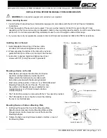
INSTALLATION AND OPERATING INSTRUCTIONS
CAUTION: The maximum load capacity is 165lbs. Use with products exceeding the maximum load capacity may cause
serious injury. See apparatus instructions.
It is recommended that two people perform the installation. Injury and/or damage can result from dropping or
mishandling the display.
(×4) M6×12 screw
(×4) M8×15 screw
Recommended mounting surfaces: wood stud and solid-flat concrete. If the mount is to be installed on any surface
other than wood studs, use suitable hardware (not included but commercially available).
Prior to the installation of this product, the installation instructions should be read and completely understood. The
installation instructions must be read to prevent personal injury and property damage. Keep these installation
instructions in an easily accessible location for future reference.
When mounting to a wall that contains wood studs, confirm dead center of the wood stud prior to installation, it is
recommended that the wood studs be a minimum of 16" apart.
Caution
Do not install on a structure that is prone to vibration, movement or chance of impact. Failure to do so could result in
damage to the display and/or damage to the mounting surface.
The wall structure must be capable of supporting at least the maximum load capacity as indicated. If not, the wall must
be reinforced. Proper installation procedure by yourself or a qualified service technician, as outlined in the installation
instructions, must be adhered to. Failure to do so could result in serious personal injury.
Hardware kit:
(×4) M5×30 screw
(×4) M8×30 screw
(×4) M6×30 screw
(×4) Spacer
(×4) M5×12 screw
2
Summary of Contents for Low Profile Universal TV Mount - 42" to 70
Page 6: ...Blank Page 6...