background image


8


FIRMWARE UPDATE 

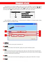
This  section  is  for  technical  support  only.  Do  not  try  The  definition  of  rotary  switch  is  listed 

below. When the user is going to do firmware update, please set the rotary switch from O to F first. 
Once the procedure is done, please switch it back to 0. Normally, user should keep the position of 
the rotary switch at 0. The other positions are reserved for other uses in the future. 


Rotary Switch Position 

Description 

Normal Operation 

Main Board firmware Update 

1~E 

Reserved [Don’t select] 


After  setting  the  rotary  switch  to  F  and  executing  the  software  for  firmware  update.  Please 

follow the steps to do firmware update. 


1.


COM Port 
Please choose the correct port connected to PC.   


2.


Load File 
Point out the location of the file which is going to be used for firmware update. 
 

3.


Burn 
Press the button first to enter the standby mode. After user reboot the device, the system will 
start to procedure firmware update automatically. When the procedure is done, RS-232 between 
the device and PC will be disconnected. 
 

4.


Cancel 
When the user wants to terminate the updating process, please press this button is to leave. 
 

5.


Encrypt 

Summary of Contents for AV-GM06M3-S1

Page 1: ...5x64 HDMI Splitter in Modularized HDMI Cat X Out P N AV GM06M3 S1 ...

Page 2: ...rvice this unit yourself except where explained in this manual Provide proper ventilation and air circulation and do not use near water Keep objects that might damage the device and assure that the placement of this unit is on a stable surface Use only the power adapter and power cords and connection cables designed for this unit Do not use liquid or aerosol cleaners to clean this unit Always unpl...

Page 3: ... cable can actually be extended up to 20 meters 66 feet long under Full HD and make the overall transmission distance superior than regular HDMI splitters or matrix switches in the market FEATURES State of the art Silicon Image founder of HDMI chipset embedded for utmost compatibility and reliability Support HDMI Deep Color 3D HDCP compliant PCIe card slot compatible design Each HDMI PCIe card pro...

Page 4: ...ction Human body X 19kV air gap discharge 12kV contact discharge PCB stack up 4 layer board impedance control differential 100Ω single 50Ω Input Main 5x HDMI Sub up to 8x HDMI Output Up to 64x HDMI or RJ45 combined HDMI connector Type A 19 pin female RS232 connector DE 9 9 pin D sub female DIP switch EDID setting Rotary control switch Firmware update Mechanical Housing Metal enclosure Dimensions L...

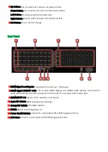
Page 5: ...ANEL DESCRIPTIONS Front Panel 1 Power On Off Button Turn On Off the power 2 Main Source Select Use to select the HDMI source of 5x1 switcher main board 3 Sub Input Select Select input mapping to the main source or local input 4 VFD Menu Menu for showing selected item or status The number of HDMI or cat 5 5e 6 is depended on the daughter boards ...

Page 6: ...rom Group 1 to Group 8 8 HDMI Signal OUTPUT 1 64 Link to each HDMI display via a HDMI cable directly or Cat 5e 6 7 cable with a HDMI over CAT5e receiver CV 735 or CV 715s on each CAT5 output port 9 HDMI INPUT 1 5 Inputs of 5x1 switcher main board 10 2 pin DIP Switch EDID audio video settings 11 Rotary DIP Switch Firmware Update 12 RS232 RS232 Control Signal to PC 13 Power On Off Switch Connect to ...

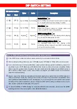
Page 7: ...surround sound 3 If you encounter any unsolved audio video output problem during system installation please turn any Mode to pin 1 OFF pin 2 ON for safe mode to enforce the most compatible 1080p stereo output for system check However the safe mode cannot be initiated if your HDMI source is set to enforce 1080p output In this case please reconfigure your HDMI source to all resolution output for tro...

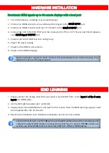
Page 8: ... LEARNING 1 Please connect the display which the user want to learn EDID from to the Input 1 of the 5 main inputs via HDMI cable 2 Set the DIP switch position pin 1 at ON 3 Please reboot the AV GM06M3 S1 and wait for 30 seconds Then the EDID learning sequence will be completed after the 30 seconds 4 Resume the installation see Hardware Installation section for more detail Step7 and step8 is import...

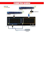
Page 9: ...7 CONNECTION DIAGRAM ...

Page 10: ...re Update 1 E Reserved Don t select After setting the rotary switch to F and executing the software for firmware update Please follow the steps to do firmware update 1 COM Port Please choose the correct port connected to PC 2 Load File Point out the location of the file which is going to be used for firmware update 3 Burn Press the button first to enter the standby mode After user reboot the devic...

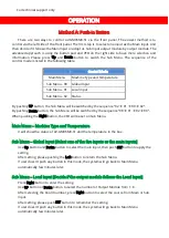
Page 11: ...l be switched by the sequence 00 01 02 00 When pushing the Right button the VFD will be set on Sub Menu Main Menu Machine Type and Temperature It will show the status of AV GM06M3 S1 and the temperature in the box Sub Menu Global Input Select one of the five inputs as the main inputs Use Up button and Down button to select the main input then push SET button to apply the setting After setting plea...

Page 12: ...Show the Global Local input for each output module Use UP button and Down button to switch the information If user doesn t push any button in this mode the system will go back to Main Menu automatically few minutes later ...

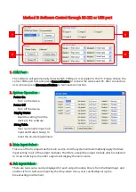
Page 13: ...om the device to the software String Table User can rename Input Sub Input and Output Group to meet the on site requirement 3 Main Input Select Tick one of the five Inputs as the main source And the system will automatically apply the Main Input setting to all of the output modules Therefore except the output module which is selected to its own Sub Input the other outputs will display the main sou...

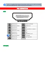
Page 14: ...erved N C on device Pin 5 TMDS Data1 Shield Pin 15 SCL Pin 6 TMDS Data1 Pin 16 SDA Pin 7 TMDS Data0 Pin 17 DDC CEC Ground Pin 8 TMDS Data0 Shield Pin 18 5V Power Pin 9 TMDS Data0 Pin 19 Hot Plug Detect Pin 10 TMDS Clock CAT5 RJ45 If there is no daughter board inserted into the output module port the software will disable the corresponding drop down menu to avoid any misunderstanding ...

Page 15: ...13 ...
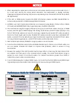
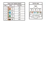
Page 16: ...es A solid UTP Cat 5e cable shows longer transmission range than stranded STP Cat 6 cable For long extension applications solid UTP STP cables are the only viable choice 5 EIA TIA 568 B termination T568B for category cables is recommended 6 To reduce the interference among the unshielded twisted pairs of wires in Cat 5 5e 6 cable one can use double shielded STP cables to improve EMI problems which...

Page 17: ...amage in transit Under no circumstances will a unit be accepted without a return authorization number The warranty is in lieu of all other warranties expressed or implied including without limitations any other implied warranty or fitness or merchantability for any particular purpose all of which are expressly disclaimed Proof of sale may be required in order to claim warranty Customers outside Ta...

Reviews: