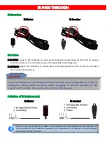
SIIG AV-GM04Q3-S1 Manual Download Page 9


7


IR PASS-THROUGH 

IR Extenders 

IR Blaster 

IR Receiver 


IR Sockets 

IR BLASTER:  plug  in  the  IR  blaster  to  emit  all  IR  command  signals  received  from  the  IR  receiver 

from the other enf to control the devices corresponding to the IR signals. 

IR RECEIVER: plug in the IR receiver to receive all IR command signals from the IR remote controls of 

the corresponding devices. 


Definition of IR Earphone Jack 

IR Blaster 

IR Receiver 


You can buy any IR extension cables in the market that are compatible to the definition of 
the IR sockets for the extender if necessary for replacement use. However, IR cables longer 
than 2m (6-ft) may not work. 

Incorrect placement of IR Blaster and Receiver may result in the failure of the IR 

extenders.  Please  check  carefully  before  plugging  in  the  IR  extender  to  the 

respective IR sockets. Warranty will not cover the damage.


CAUTION!   


Summary of Contents for AV-GM04Q3-S1

Page 1: ...HDMI over IP Multicast System with PoE support TX RX...

Page 2: ...self except where explained in this manual Provide proper ventilation and air circulation and do not use near water Keep objects that might damage the device and assure that the placement of this unit...

Page 3: ...ith 802 1Q VLAN function which provides control remotely so multi video and source allowed and supported FEATURES Supports resolution up to 1080p60 HDMI v1 3 compliant HDCP 1 4 compliant Supports audi...

Page 4: ...on 1 Human body model 19kV air gap discharge 12kV contact discharge 2 Core chipset 8kV PCB stack up 4 layer board impedance control differential 100 single 50 IR pass thru Yes RS 232 support Yes Input...

Page 5: ...ty 20 90 RH no condensation PANEL DESCRIPTIONS Transmitting unit AV GM04Q3 S1 TX Front Panel 1 5V DC Connect to 5V DC power supply optional 2 RS 232 Connect to PC serial port with a DSUB 9 male male c...

Page 6: ...sion cable of IR receiver 14 HDMI OUT Connect to a HDMI display with a HDMI male male cable 15 S PDIF Output TOSLINK 16 Stereo Output 3 5mm Rear Panel 17 5V DC Connect to 5V DC power supply optional 1...

Page 7: ...Pin5 Pin6 ID Pin1 Pin2 Pin3 Pin4 Pin5 Pin6 0 32 1 33 2 34 3 35 4 36 5 37 6 38 7 39 8 40 9 41 10 42 11 43 12 44 13 45 14 46 15 47 16 48 17 49 18 50 19 51 20 52 21 53 22 54 23 55 24 56 25 57 26 58 27 59...

Page 8: ...6 CONNECTION DIAGRAM...

Page 9: ...controls of the corresponding devices Definition of IR Earphone Jack IR Blaster IR Receiver You can buy any IR extension cables in the market that are compatible to the definition of the IR sockets f...

Page 10: ...age in transit Under no circumstances will a unit be accepted without a return authorization number The warranty is in lieu of all other warranties expressed or implied including without limitations a...

Reviews: