background image

2. SAFETY PRECAUTIONS 

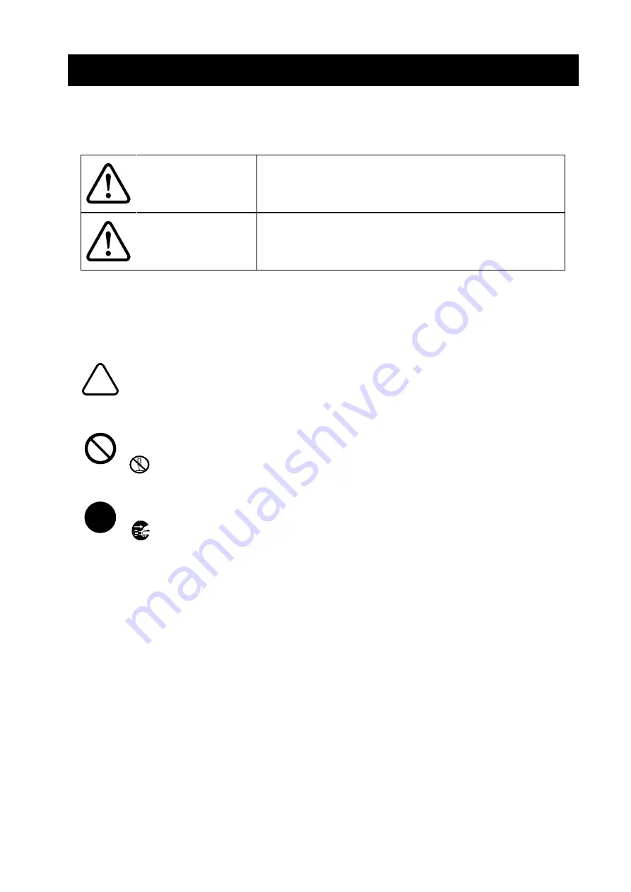
In this SAFETY PRECAUTIONS, the following symbols are used to ensure safe and proper use of 

products and prevent from damaging devices. 


WARNING


Failure to follow the instructions marked with this symbol could 

result in severe personal injury or death.


CAUTION


Failure to follow the instructions marked with this symbol could 

result in minor personal injury or property damage. 


About symbols 


The symbol indicates information which you should pay attention to (including danger 

and warnings). 


The symbol indicates information about prohibited procedures. 


      indicates "Disassembly is prohibited." 


The symbol indicates information about obligated or instructed procedures. 


      indicates "Unplug the power plug from the outlet." 


Summary of Contents for SLP720RT Series

Page 1: ...USER S GUIDE Thermal Printer SLP720RT SERIES Read this USER S GUIDE carefully before using the printer Keep this USER S GUIDE in a place where it can be accessed quickly ...

Page 2: ...heir respective companies Applicable EC Directive and Standards Product Thermal Printer SLP720RT Model with WLAN with AC adapter PW H2415 W1 Directive Title 2014 53 EU Radio Equipment Directive 2009 125 EC Directive on Eco Design of Energy related Products 2011 65 EU Commission Delegated Directive EU 2015 863 Restriction of the use of certain hazardous substances RoHS Directive Standards EN 301 48...

Page 3: ...EN 301 489 1 BS EN 301 489 17 BS EN 300 328 BS EN 62368 1 BS EN IEC 63000 BS EN 623111 Restrictions This product is for use only with nominal voltage in each country Product Thermal Printer SLP720RT with AC adapter PW H2415 W1 Directive Electromagnetic Compatibility Regulations 2016 Electrical Equipment Safety Regulations 2016 The Ecodesign for Energy Related Products and Energy Information Amendm...

Page 4: ...e to radio or television reception which can be determined by turning the equipment off and on the user is encouraged to try to correct the interference by one or more of the following measures Reorient or relocate the receive antenna Increase the separation between the equipment and receiver Connect the equipment into an outlet on a circuit different from that to which the receiver is connected C...

Page 5: ...here it can be accessed quickly This manual consists of the following sections 1 INTRODUCTION 1 2 SAFETY PRECAUTIONS 2 3 OPERATING PRECAUTIONS 5 4 PREPARATION 8 5 IDENTIFYING MODEL TYPE 9 6 EACH PART OF PRINTER 10 7 POWER CONNECTION 14 8 LOADING THERMAL PAPER 15 9 PREVENTION AND TREATMENT OF PAPER JAM 20 10 TEST PRINT 22 11 FUNCTION SETTINGS 25 12 CONNECTING TO HOST DEVICE 28 13 PRINTER MAINTENANC...

Page 6: ... or death CAUTION Failure to follow the instructions marked with this symbol could result in minor personal injury or property damage About symbols The symbol indicates information which you should pay attention to including danger and warnings The symbol indicates information about prohibited procedures indicates Disassembly is prohibited The symbol indicates information about obligated or instru...

Page 7: ... Keep the terminals of the products power connector AC plug and DC plug away from dust and metal objects Make sure the AC plug and DC plug are securely plugged in when using the products DO NOT damage the AC cable AC plug and DC plug DO NOT bend pull twist the cable forcibly or place heavy stuff on it Be sure to observe the following instructions Failure to follow the instructions may lead fire el...

Page 8: ...the AC plug from the outlet when not in use for a long time or before maintenance DO NOT use or store the products in the following locations Locations exposed to direct sunlight or high temperature Locations exposed to high humidity a lot of dust and liquid Locations subject to strong vibration or unstable locations DO NOT cover the products with a cloth when in use NEVER touch the thermal head i...

Page 9: ...by hand with the thermal paper loaded DO NOT open the top cover during printing or cutting DO NOT connect or disconnect the interface cable during printing or communication DO NOT touch the plug of the interface cable during printing When handling the printer be aware of static electricity When the static electricity is discharged this could cause a USB communication failure When this problem occu...

Page 10: ...t from the installation surface Lifting it rapidly or moving it horizontally may peel the entire rubber feet peel their surfaces or damage the outer case When something goes wrong with the printer during use stop using it immediately and unplug the AC plug from the outlet NEVER disassemble the printer without a serviceman Precautions for Wireless communication The Wireless LAN model using IEEE802 ...

Page 11: ...k the thermal paper with diazo copies immediately after copying DO NOT use chemical glue DO NOT use 2 ply thermal paper and perforated thermal paper Precautions on Discarding When discarding used products discard them according to the disposal regulations and rules of each district Notation The following 2 types of notation are used throughout this manual to denote operating precautions and items ...

Page 12: ...n or long term storage Safety Precautions Quick Start Guide Printer Sample Thermal Paper AC Adapter AC Cable USB Cable USB model only The available accessories are shown below See 15 SPECIFICATIONS and 16 ACCESSORIES AND CONSUMABLE PARTS and be sure to purchase our specified products listed on these references AC Adapter AC Cable USB Cable ...

Page 13: ...Unspecified other than Wireless LAN model When the printer is incorporated into your equipment and then supplied electric power from the equipment follow the rated value of input voltage for SLP720RT described in the printer specifications of 15 SPECIFICATIONS When using a power supply other than the specified AC adapter use a power supply at your own risk under the safety standard and EMC regulat...

Page 14: ...10 6 EACH PART OF PRINTER 1 2 3 4 5 6 7 8 11 10 9 12 13 16 14 15 15 14 14 15 ...

Page 15: ...l head The thermal head prints data on the thermal paper NEVER touch the thermal head with hands immediately after printing because it may get hot 9 Black mark sensor The sensor detects thermal paper presence and the black mark 10 Taken sensor The sensor detects the removal of thermal paper When Taken Mode is Enable the next printing starts after removing the previous paper remaining in the paper ...

Page 16: ...over open error Lime yellow On Hardware error Red On Head temperature error Purple On Voltage error Purple Blink 1 Cutter error Purple Blink 2 Not connected Wireless LAN communication Blue Blink 2 Paper removal waiting Blue Blink 3 Rewriting firmware White On 1 The color tone may vary depending on the individual difference of the products and the viewing angle 2 The value at the shipping LED Blink...

Page 17: ...pen Close the top cover 4 Cutter error Cut failure due to paper jam at cutting Open the top cover to remove the error cause and close the top cover the printer automatically recovers If the top cover is not open or the printer does not automatically recover see Clearing Cutter Error in 9 PREVENTION AND TREATMENT OF PAPER JAM 5 Voltage error The power voltage is out of the allowable range The print...

Page 18: ...r Pull How to unlock the DC plug Plug the AC plug of the AC cable to an outlet NOTE Plug the DC plug into the power connector of the printer in the correct orientation When plug the DC plug forcibly in wrong orientation it may cause damage Unplug the AC plug of the AC cable from the outlet when inserting or pulling out the DC plug The printer power connector has the locking system Pull the DC plug...

Page 19: ...release lever of the printer upward and open the top cover Slide the paper guide while pulling the lever of the paper guide upward NOTE Set the paper width before using the printer for the first time DO NOT change the paper width after starting to use the printer Doing so may damage the printer When the thermal paper smaller than 58 mm in width is used rubber crumbs of the platen may be generated ...

Page 20: ...om the thermal paper Load the thermal paper into the paper holder NOTE DO NOT touch the cutter blade directly Make sure not to injure your body or other objects as the sheet metals around the thermal head and the cutter have sharp edges Pull the thermal paper straight Make sure that the thermal paper does not slant ...

Page 21: ...over the paper outlet or hold down the thermal paper ejected Doing so may cause a paper jam DO NOT touch the platen Doing so may cause loss of printing quality or damage HINT Leaving the printer with the thermal paper for a long time may cause a paper feeding problem because the surface of the thermal paper sticks to the thermal head in the case of linerless label the adhesive sticks to the platen...

Page 22: ...e end is glued taped or folded Use the thermal paper whose core outside diameter is φ12 mm or more for receipt and φ18 mm or more for label paper CORRECT INCORRECT CORRECT NOTE DO NOT use deformed thermal paper Doing so may cause the printer damaged CORRECT INCORRECT NOTE In the case of using loosened thermal paper roll rewind the roll before using it ...

Page 23: ...ble Enable 3 Green Linerless label Enable Enable 4 Green SLP Label Enable Disable 5 Aqua Receipt Disable Disable 6 Blue The LED turns to the lighting of Standby LED color NOTE The LED Color of the printer status Power on print ready Connecting Wireless LAN communication changes to the color of Standby LED that is set in easy paper setting See LED Indication described in 6 EACH PART OF PRINTER for ...

Page 24: ...paper remaining in the paper outlet When printing continuously on receipt or SLP Label set MS1 2 Taken Mode Selection to Disable See 11 FUNCTION SETTINGS for details DO NOT touch the thermal paper during operating Clearing Paper Jam When a paper jam occurs remove the thermal paper according to the following procedure Turn off the printer Operate the release lever to open the top cover and remove t...

Page 25: ...ere is a paper jam remove it Set the thermal paper straight and then close the top cover gently Turn on the printer When the printer is recovered normally the LED turns blue NOTE DO NOT use such as ballpoint pens drivers and cutter knives to remove a jammed paper Be careful not to damage the printer Especially do not touch the thermal head because it is easy to break Be careful not to cut your fin...

Page 26: ...rinter as instructed in 8 LOADING THERMAL PAPER Ensure that no error occurs and then turn off the printer Hold the FEED Switch down and press the POWER Switch then release the POWER Switch Release the FEED Switch when the test print has been started The printer cuts the paper and returns to the print ready status when the test print has completed Figure 10 1 Test Print Example USB Model ...

Page 27: ...AC Address MAC Address IP Address IP Address Subnet Mask Subnet Mask GateWay Address Gateway Address DHCP Client Selected DHCP Client Mode Physical Layer Selected Communication Speed and Communication Mode Figure 10 2 Test Print Example Ethernet USB Model ...

Page 28: ...Selected Security DHCP Selected DHCP Client Mode in Client Mode MAC Address MAC Address IP Address IP Address Subnet Mask Subnet Mask Default Gateway Gateway Address Figure 10 3 Test Print Example Wireless LAN Model When Client Mode is selected in the Mode IP address Subnet Mask and Gateway Address obtained from DHCP Server are printed When the Power SW is pressed and canceled data queue is printe...

Page 29: ...rinter driver For iOS and Android App SII Printer Utility provided by App Store or Google Play Procedure for Setting Functions Using Switches To set the functions using the switches set the printer in the Setting Mode To enter the Setting Mode follow the procedure below Load the thermal paper in the printer as instructed in 8 LOADING THERMAL PAPER Ensure that no error occurs and then turn off the ...

Page 30: ...ch the number of times corresponding to the selected function number and then press the POWER Switch When pressing the FEED Switch 3 times 3 Standby LED is selected When pressing the POWER Switch without pressing the FEED Switch 0 Return to MS Selection is selected Figure 11 3 Function Selection Message Example Selected MS1 MS Selection 0 Exit 1 MS1 2 MS4 3 MS5 4 MS6 5 MS7 6 MS13 7 MS17 8 I F Sett...

Page 31: ...the FEED Switch to save the setting value to the memory Figure 11 2 is printed Press the POWER Switch to discard the selected item A message of the function selection is printed as an example shown in Figure 11 3 If select 0 Return to MS Selection there function selection is not performed and Figure 11 2 is printed To continue to set functions return to 4 To exit the Setting Mode select 0 Exit in ...

Page 32: ...F11 Each interface cables are required separately for communication with the USB interface or Ethernet interface See 15 SPECIFICATIONS for details of interface specifications The communication speed may be decreased depending on processing by software or print contents USB Interface Ethernet Interface Ensure that the printer is off Connect the interface cable to use to the interface connector on t...

Page 33: ... line to the interface connector When connecting an outdoor aerial wired LAN cable be sure to use it through another anti serge device Otherwise the device may be damaged by induced lightning For Ethernet interface DHCP client function is set to Enable At the shipping When connecting to a network that does not have the DHCP server function set the DHCP client function to Disable ...

Page 34: ...inter setting screen is displayed Make necessary settings These settings are enabled after rebooting 3 Check the communication state on the host device 4 Send data from the host device and verify that the data is printed correctly WARNING The printer may affect medical or other electronic devices Obtain information and data concerning influence due to radio interference from the respective manufac...

Page 35: ...ng on the thermal head dries out completely and then close the top cover Figure 13 1 Cleaning Thermal Head Platen Rubber Feet NOTE Clean the thermal head after it cools down Be sure to wipe the thermal head with a cotton swab or other soft material DO NOT touch the cutter blade directly Make sure not to injure your body or other objects as the sheet metals around the thermal head and the cutter ha...

Page 36: ...he interface cable connected correctly Do the specifications of the interface cable conform to its specifications of this manual Does the used interface conform to the printer Is the Wireless LAN status normal Is the communication condition between the printer and the host device correct Is the specified thermal paper being used Is the paper orientation surface back correct An error is shown See L...

Page 37: ...ure 5 C to 45 C 41 F to 113 F Relative humidity 2 10 RH to 90 RH Dimensions W D H 90 mm 200 mm 141 mm 3 Mass Approx 1100 g excluding the thermal paper Input voltage DC24 0 V 10 Current consumption 4 Waiting Approx 36 mA avg Printing print rate 25 Approx 4 8 A max Printing print rate 100 Approx 5 7 A max Power consumption Power off state SLP720RT U 0 182 W SLP720RT E 0 454 W SLP720RT W 0 220 W 1 Th...

Page 38: ...luding the cable Interface Specifications USB interface specifications Item Specification Version Ver 2 0 Printer data transmission mode Bulk transfer 12 Mbps Ethernet interface specifications Item Specification Communication standard 10Base T 100Base TX Wireless LAN interface specifications Item Specification Communication standard IEEE802 11b g n IEEE802 11a n Network configuration Infrastructur...

Page 39: ...T EK2F11 05 SLP720RT WK2FE1 05 CB CE05 20A Turkey SLP720RT UK2F11 15 SLP720RT EK2F11 05 SLP720RT WK2FE1 05 UK SLP720RT UK2F11 19 SLP720RT EK2F11 09 SLP720RT WK2FE1 09 CB UK04 20A USA Canada SLP720RT UK2F11 13 SLP720RT EK2F11 03 SLP720RT WK2FU1 03 CB US06 20A Brazil SLP720RT UK2F11 13 SLP720RT EK2F11 03 2 1 Ask your SII sales representative when you want to operate the products in countries regions...

Page 40: ... 58 MAXStick MS214170PLUSD C 58 MAXStick MS214170PLUSD P 58 MAXStick MS214170PLUSD 58 MAXStick MS214170X2 58 MAXStick MS11732270X2HRHT 40 Iconex 9023 1823 58 Iconex 9023 2242 58 Iconex 9016 3257 40 Iconex 9023 1233 40 Iconex 9023 1873 40 Iconex 9023 2150 40 StickyPOS BT format 58mm x 4in dia roll 58 StickyPOS BTX format 58mm x 4in dia roll 58 StickyPOS BT format 40mm x 4in dia roll 40 StickyPOS BT...

Page 41: ... Auto Activation by AC Disable Enable 1 8 POWER Switch Function Selection Power SW Disable Enable 1 When printing continuously on linerless label set to Enable 2 When printing continuously on receipt or SLP Label set to Disable General Setting 4 MS Function Value 0 1 4 1 to 3 Reserved Fixed 4 4 Paper Width Selection Paper Width 40 mm 58 mm 4 5 Reserved Fixed 4 6 Paper Auto Detection Selection Pape...

Page 42: ...dle 00B Disable 01B Stamp cut Stamp cut 10B Initial cut Standard 11B Disable 5 8 Cutting Mode Selection After Paper Setting Cutting Method Partial cut Partial Full cut Full General Setting 6 MS Function Value 0 1 6 1 to 8 Print Density Selection Print Density 00000000B 70 00000001B 75 00000010B 80 00000011B 85 00000100B 90 00000101B 95 00000110B 100 00000111B 105 00001000B 110 00001001B 115 000010...

Page 43: ...ction Maximum Feeding Length Setting MS10 Lower 8 bits MS11 Higher 8 bits Total of higher 8 bits and lower 8 bits 1 to 300 dots Default 190 Mark Detection Threshold Value MS Function Value 0 1 12 1 to 8 Mark Detection Threshold Value 01h to EFh Default 80h Command Setting MS Function Value 0 1 13 1 Kanji Code System Selection Kanji Code Shift JIS Code JIS Code 13 2 Reserved Fixed 13 3 Realtime Com...

Page 44: ...de Table Setting Character Code Table 00000000B USA Standard Europe Code Page437 00000001B Katakana 00000010B Multilingual Code Page850 00000011B Portuguese Code Page860 00000100B Canadian French Code Page863 00000101B Nordic Code Page865 00001101B Turkish Code Page857 00001110B Greek Code Page737 00001000B Latin Code Page1252 00001001B Russian Code Page866 00001010B Eastern Europe Code Page852 00...

Page 45: ... to 2 Paper Saving Setting Paper Saving 00B Space Between Lines 0 dots 01B Space Between Lines 2 dots 10B Space Between Lines 4 dots 11B Disable 17 3 Feed Backward Setting After Paper Cutting Backfeed After Cut Enable Disable 17 4 to 8 Reserved Fixed ...

Page 46: ... 1 310 517 7779 Seiko Instruments GmbH Economic operator Siemensstrasse 9 D 63263 Neu lsenburg Germany Telephone 49 6102 297 0 Facsimile 49 6102 297 222 Commercial registration number 5 HRB 8309 info seiko instruments de Seiko Instruments H K Ltd 4 5 F Wyler Center 2 200 Tai Lin Pai Road Kwai Chung N T Kowloon Hong Kong Telephone 852 2494 5160 Facsimile 852 2424 0901 Download page https www sii co...

Reviews: