background image


Rev 1.5 

SignalFire Telemetry 


8


Configuration


Using the SignalFire Toolkit


The SignalFire Toolkit application can be downloaded at 

www.signal-fire.com/customer

After installation, launch the software and the main toolkit window will open: 


Select the COM port associated with the Wireless IO Module Mini 

and click “Auto

-Detect Device on 

COM Port.” This will open the device configuration window, where all device settings can be 

configured. 
 

Network Settings 

The network is set using the SignalFire Toolkit. To join a SignalFire network in Node mode, all Wireless 
I/O Module Minis must have the same Radio Network, Radio Network Group, and Corporate 
ID/Encryption Key as the Gateway. For two Wireless I/O Module Minis to communicate in Point-to-
Point mode, they must share the same Radio Network, Radio Network Group, and Corporate 
ID/Encryption but not share those settings with any other SignalFire network. 
 

To use an Encryption Key in lieu of a Corporate ID, check off the “Enable Encryption” box under t

he 

Corporate ID. The Corporate ID field will switch over to an Encryption Key field. 
 
The encryption key can be hidden so it cannot be read. This is the 
most secure option, but if you forget your key, there is no way to recover it 

 you have to reset the 

key on every device on its network. To enable this option, select 

Set Encryption Key Unrecoverable


under the 

Settings

 menu. 


Summary of Contents for Wireless I/O Module Mini

Page 1: ...tal I O to a SignalFire Gateway or mirror the digital I O wirelessly another Wireless I O Mini Module acting as a wire replacement The SignalFire Wireless I O Module Mini has the following features 1 Analog input 1 5V 2 Digital inputs 2 Relay outputs 2 SPDT Wide range DC power input 6 36 VDC Low power consumption DIN rail mount with pluggable screw terminal blocks Status LEDs ...

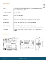
Page 2: ... Analog Input 0 5V Signal 10V Max Digital Inputs Dry Contact or 30 Volts Max push pull 2kHz maximum frequency Digital Outputs 2 SPDT s max 30 VDC 2 Amps 250 VAC 0 25 Amps Radio Frequency Compliance 902 928MHz ISM Band FHSS radio RP SMA connector FCC and IC Certified Contains FCC ID W8V SFTS500 IC 8373A SFTS500 Certified for use in Class I Division 2 Groups A B C D Temperature Code T5 ...

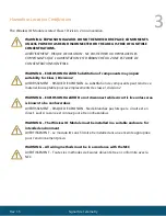
Page 3: ...ISSEMENT RISQUE D EXPLOSION La substitution de composants peut rendre ce materiel inacceptable pour les emplacements de classe I division 2 WARNING EXPLOSION HAZARD Do not disconnect while circuit is live unless area is known to be nonhazardous AVERTISSEMENT RISQUE D EXPLOSION Ne débranchez pas lorsque le circuit est en direct sauf si la zone est connue pour être nonhazardous WARNING The Wireless ...

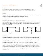
Page 4: ...input terminal to ground to convert the signal to 1 5V 1 5V Signal GND 4 20mA Signal GND A Input 1 A Input 1 Digital Inputs The digital inputs 2 total can be dry contact or voltage must be push pull and pull to ground 30 Volts max Be sure to connect the ground bus from the module to either the ground of the voltage device or the dry contact The digital inputs report their current state as well as ...

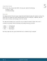
Page 5: ...tatus LED also indicates the signal strength between it and its module pair In addition there are TX RX LEDs to indicate radio messages to from the module The status LED will blink once a second if it is not connected to another module If the node is connected to its paired module it will blink a link quality code every 3 seconds 3 Blinks Strong Signal 2 Blinks Good Signal 1 Blink Weak Signal Each...

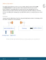
Page 6: ...ll WIOM Minis on the network must be set to Node and they will communicate with a SignalFire Gateway For Point to Point set one WIOM Mini to Gateway and one WIOM Mini to Node on a network that has no other devices Node Mode In Node mode the WIOM Mini will send its analog and digital inputs outputs to the Gateway All IO and then be read set from a PLC via Modbus Node Mode The Gateway reads all inpu...

Page 7: ...put the analog input is not used Point to Point Mode Inputs from one module are mirrored as outputs on the other When set to Point to Point mode the WIOM Minis will not be viewable through a SignalFire Gateway as they will be on their own network The module that is set to Gateway will be locked to Slave ID 1 WIOM Mini to WIOM Mode A WIOM Mini and a regular WIOM can also operate in Point to Point m...

Page 8: ...ave the same Radio Network Radio Network Group and Corporate ID Encryption Key as the Gateway For two Wireless I O Module Minis to communicate in Point to Point mode they must share the same Radio Network Radio Network Group and Corporate ID Encryption but not share those settings with any other SignalFire network To use an Encryption Key in lieu of a Corporate ID check off the Enable Encryption b...

Page 9: ...ire Gateway If used this timeout must be set higher than the Modbus coil write frequency of the Modbus master device This option is available for both Point to Point and Node mode Analog Scaling Node Mode only Analog scaling can be used to scale an analog input to engineering units For example for a 0 1000psi sensor set the scale low to 0 and scale high to 1000 The scaled value will now be display...

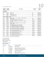
Page 10: ...04 41105 Relay 2 State 03 04 Read Only 1105 41106 AI1 Scaled Reading Float High Word 03 04 Read Only 1106 41107 AI1 Scaled Reading Float Low Word 03 04 Read Only 1107 41108 DI1 Total Counts Unsigned int High Word 03 04 Read Only 1108 41109 DI1 Total Counts Unsigned int Low Word 03 04 Read Only 1109 41110 DI2 Total Counts Unsigned int High Word 03 04 Read Only 1110 41111 DI2 Total Counts Unsigned i...

Reviews: