


-1-
TABLE OF CONTENTS
GENERAL DESCRIPTION
2
INSTALLATION
2-10
INSTALLER -SELECTABLE OPTIONS
3-4
MOUNTING
5
ELECTRICAL CONNECTIONS
5-10
Siren Electrical Connections
6-7
Siren Wiring Diagram
8
Lighting Electrical Connections
9
Lighting Wiring Diagram
10
OPERATION
11-13
LIGHT SLIDE SWITCH
11
LIGHT PUSH BUTTON SWITCHES
11
SELECTOR SWITCH
12
MANUAL AND HORN BUTTONS
12-13
VOLUME CONTROLS
14
MICROPHONE
14
AUXILIARY INPUT
14
PARK KILL
14
SPEAKER DIAGNOSTICS
14
SERVICE
15-18
FUSES
15
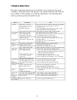
TROUBLESHOOTING
16
PARTS
17
SPECIFICATIONS
17
LIMITED WARRANTY
18
NOTICE
Due to continuous product improvements, we must reserve the right to change any specifications and
information, contained in this manual at any time without notice. Signal Vehicle Products makes no
warranty of any kind with regard to this manual, including, but not limited to, the implied warranties of
merchantability and fitness for a particular purpose. Signal Vehicle Products shall not be liable for errors
contained herein or for incidental or consequential damages in connection with the furnishing,
performance, or use of this manual.
INSTALLATION INFORMATION
MODEL :
LCS770
SERIAL #:
PURCHASE DATE:
INSTALLER:
DEALER:
INSTALLATION DATE:
OPTION JUMPERS
Negative Auxiliary Switching
Audible Beep disable
Negative Park Kill Switching
8 sec. gun lock S4
Two-Tone Enabled
Auxiliary Override
Phaser Disabled
Pursuit Disable
Model and serial number located on bottom of unit