


-9-
Wire Size and Termination
The wiring diagram on the next page shows the minimum wire size used for each
connection, along with recommended lead color. Please use the following
guidelines when wiring your siren:
•
If the wire is longer than 10 ft. use the next larger wire size. Use only high quality
crimp connectors.
•
Make sure all connections are tight.
•
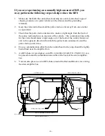
Route the wiring to prevent wear, overheating and/or interference with air bag
deployment.
•
Use grommets and sealant when passing through compartment walls.
•
Minimize the number of splices to reduce voltage drop.
•
Ground connections should only be made to substantial chassis components, preferably
directly to the negative of the vehicle battery.
•
Install and check all wiring before connection to vehicle battery.
Wiring Connections:
BLACK LEADS:
You MUST connect BOTH black wires when using two 100W driver speakers.
Connect to the negative of the battery, or to a good chassis ground. Be sure to use
minimum size #14 AWG wire.
RED LEADS:
You MUST connect BOTH red wires when using two 100W driver speakers.
Connect to the positive of the battery, or to a high current power buss. A power relay
may also be used. Be sure to use minimum size #14 AWG wire.
BROWN LEAD:
Connect brown lead to positive terminal or lead of the first speaker. Be sure to use
minimum size #14 AWG wire. (Speaker #1)
WHITE LEAD w/ BROWN STRIPE:
Connect lead to negative terminal or lead of the first speaker. Be
sure to use minimum size #14 AWG wire.
Please note:
The Brown and White w/Brown Stripe wire must be connected for PA and Radio Repeat)
ORANGE LEAD:
Connect orange lead to positive terminal or lead of the second speaker. Be sure to
use minimum size #14 AWG wire. (Speaker #2)
WHITE LEAD w/ ORANGE STRIPE:
Connect lead to negative terminal or lead of the second speaker.
Be sure to use minimum size #14 AWG wire.
You must observe the polarity of the speakers (phasing). Be sure the positive terminals of both speakers
are connected to the
solid
brown wire and
solid
orange wire from the siren. The negative terminals of
both speakers should be connected to the white, same color stripe,
striped
wires from the siren.
Optional Connections:
BLUE LEADS:
Use for radio repeat. Connect one blue lead to each terminal of the radio speaker or
output connector of the radio. Most radio outputs are isolated, in which polarity would
not be important. Radios with polarity sensitive outputs should be connected w/ the
blue wire from pin 6 to the positive radio output, and the blue wire from pin 3 to the
negative radio output. Use #18 AWG wire.
GREEN LEAD:
Use for remote (Aux.) Manual control. Connect to horn ring circuit or remote switch.
Circuit may be positive or negative with proper jumper selection. See INSTALLER-
SELECTABLE OPTIONS section (page 3) for jumper details.
NOTE:
Cut lead short
if not used & insulate w/ electrical tape.
WHITE LEAD:
Used for Park Kill (Cut -off). Connect to dome light or added door switch. Circuit
may be positive or negative with proper jumper selection. See INSTALLER-
SELECTABLE OPTION section (page 4) for jumper details.
NOTE:
Be sure to cut
lead short if not used and insulate with electrical tape.
Testing
- Test all siren functions after installation to assure proper operation. Test
vehicle operation to assure no damage to vehicle.