S-DIAS CPU UNIT
CP 733
06.12.2019
Page 17
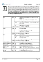
The connections of the +24 V supply (X2: pin 6 and pin 7) or the GND sup-
ply (X2: pin 8 and pin 9 and pin 10) are internally bridged. To supply the
module, only one connection to a +24 V pin (pin 6 or pin 7) and a GND pin
(pin 8 or pin 9 or pin 10) is required. The bridged connections may be used
for further looping of the +24 V supply and the GND supply. However, it
must be taken into account that a total current of 6 A per connection is not
exceeded by the forward looping!
Run
green
ON
from activation of the voltage supply until processing of the
autoexec.lsl
when the application is running (except when controlled
differently via the application )
BLINKS
In the CLI, while processing the autoexec.lsl until the applica-
tion is running
OFF
when an error or reset occurs
can be set from the application (ON, BLINKING, OFF)
Status
yellow OFF
during start process
during RUN status (application running)
when an error or reset occurs
can be set from the application (ON, BLINKING, OFF)
Error
red
ON
when error occurs
BLINKS
when an error or reset occurs
OFF
during start process
during RUN status (application running)
can be set from the application (ON, BLINKING, OFF)
Ethernet/VARAN Link
green ON
connection between the two PHYs made
Ethernet/VARAN Active
yellow ON
data is exchanged over the Ethernet bus
EtherCAT Link
green ON
Data is exchanged over the EtherCat bus
EtherCAT Active
yellow ON
connection between the two PHYs made
Battery Low
red
ON
battery is empty and should be replaced as soon as possible
CAN active
yellow BLINKS
data is being exchanged
DC OK
green ON
module is supplied with a voltage > 18 V


