


12
e)
When the loops are pulled tight, crimp the middle 1/3 of the
tube to lock the wire in place. At this point, connect metal clevis
to the middle hole on one of the rudder control horns, and slide
the pull-pull wire into the guide tube in the fuselage.
f)
Repeat steps c) through e) again to make the other pull-pull
wire, and tape the rudder in a neutral position.
g)
Attach a 2” double servo arm (not furnished) to the rudder
servo. With both of the metal clevises attached to the rudder
control horns, pull the wires through the fuselage - (an
extendable magnetic parts grabber is helpful for this step).
Attach the remaining two metal clevises to the rudder double
servo arm.
h)
After crossing the wires once, slide a crimp tube onto one of the
wires, thread the wire through the brass rigging coupler and pull
the wire snug. Using a needle-nosed pliers, pinch the wire
against the rigging coupler to mark the wire.
i)
Remove the metal clevis from the rudder control horn and
double servo arm – this will allow you to pull the wire and
rigging coupler forward enough to work with it inside the
fuselage.
j)
While keeping the wire located at the marked position, loop the
wire through the crimp tube and secure it by crimping the tube.
k)
Repeat steps h) through
j)
for the second pull-pull wire. At this
point, all four metal clevises can be connected – two to the
rudder control horns and two to the servo arm. The wires might
be slightly loose, and can be tightened by turning the brass
rigging couplers into the metal clevises. When the wires are
tight (snug, but not like guitar strings), tighten the M3 nuts
against the metal clevises on all four rigging couplers.
ELECTRIC POWER SYSTEM
Skip this section if you
’re using a glow engine power setup
For this section you will the Fuselage and:
(1) Fiberglass Cowling
(4) M3 x 10mm Screws
(1) Plywood Electric Motor Mount
(1) Plywood Battery Box
(1) Balsa Triangle Stock
(4) M4 x 20mm Socket-Head Bolts
(4) M4 Flat Metal Washers
(4) M4 x 16mm Socket-Head Bolts
(4) M4 Split-Ring Lock Washers
(4) M4 Blind Nuts
(1) Hook-&-Loop (Velcro®) Straps
(1) Electric Motor, ESC, Prop, LiPo Battery (not furnished)
❑
25)
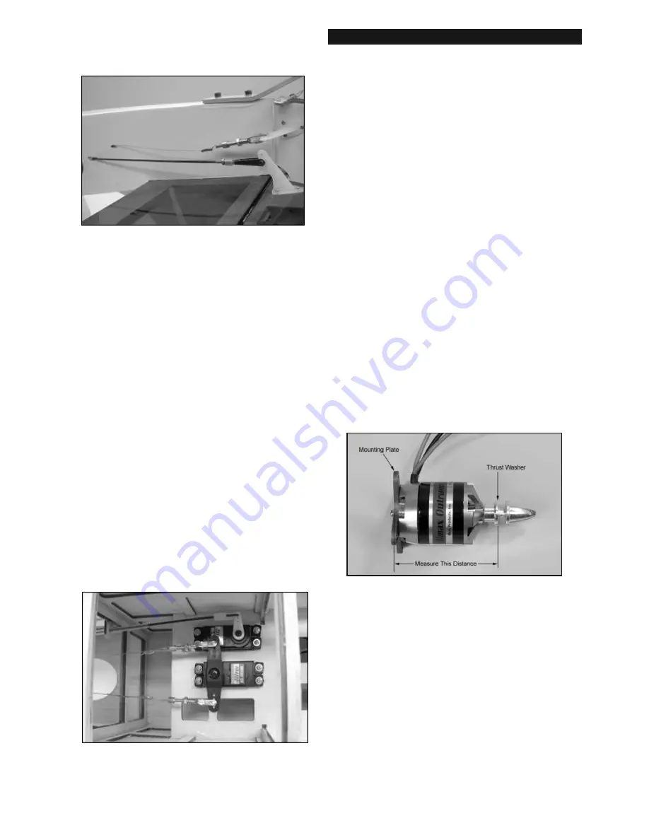
NOTE: The mounting of the electric motor in the Rascal 80
assumes that your motor has a typical "X" or "cross" mounting
plate on the back of the motor.
Also note that the firewall
portion of the laser-cut plywood Motor mount Is adjustable
fore and aft to accommodate Different length motors. In this
step we will adjust the motor mount for your particular electric
motor. For the Rascal 80 we need a total distance from the back
of the plywood motor mount box to the motor’s thrust washer
to end up exactly 5-3/8”. This distance allows the cowling to
fit properly.
a)
Assemble your motor according to the manufacturer's
instructions. Then carefully measure the distance from the back
of the mounting plate to the front of the thrust washer *.
*
The “thrust washer” is the part of the prop adaptor where
the back of the propeller will be located.
b)
Subtract the measurement taken in the previous step a) from
5-3/8”. The result is the distance you need to locate the front of
the firewall from the back of the plywood motor mount box.
(With the motor we are using in these photos, the motor
measurement is 2-3/4”. So 5-3/8” minus 2-3/4” = 2-5/8”. Your
result may be different depending on your motor.)
c)
Carefully measure and mark the distance determined in the
previous step from the back edge of the motor mount box
towards the front. Do this alongside each of the adjustment slots
on both sides of the box (four marks total).
d)
After you have all four slots marked, carefully align the front face
of the firewall to line up with the marks. Make sure you end up
with the firewall straight and square in the box. If it is not,
recheck your marks and adjust as necessary.
Summary of Contents for Rascal 80 eg
Page 1: ......