


the fuselage and aligned with the centerline of the fuselage.
Wipe off any excess glue with alcohol. Adjust as needed
and tape securely. Remove the wing and allow the glue to
cure completely.
❑
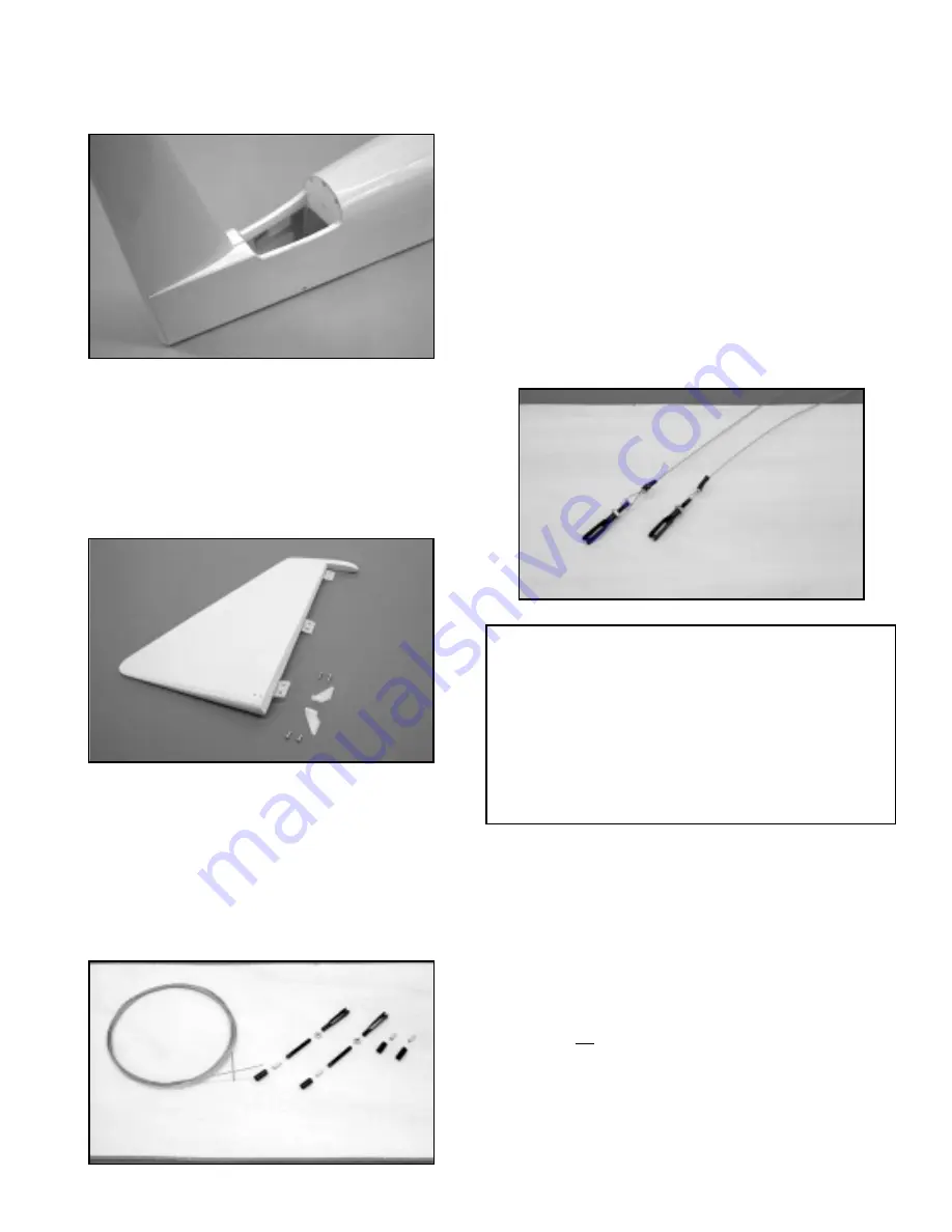
16) Install a right and left rudder horn to the bottom of the
rudder using #4 x 3/8" sheet metal screws. The rudder has
inset plywood mounting pads on each side for this purpose.
The two rudder horns directly oppose one another and
should be lined up with the pull-pull exits at the bottom rear
of the fuselage. The rudder is now hinged to the fin using
epoxy glue on the hinges - remember to protect the hinge
knuckles with petroleum jelly. Clean off any excess glue
and allow to cure.
❑
17) The rudder pull-pull system is now installed. Begin by using
your radio system to accurately center the rudder servo.
Install the output arm onto the rudder servo. From your kit
contents, locate the package containing the coil of .021
braided steel cable, rigging couplers, heat shrink tubing
and aluminum crimps.
You will also need two 4-40
threaded R/C links and two 4-40 hex nuts. Cut the braided
cable into two equal 36" lengths (a carbide cut-off wheel
works great) and cut the heat shrink tubing into four
1/2" lengths.
Place one 1/2" length of heat shrink tubing onto one end of
the cable, followed by one of the 1/2" aluminum tubes.
Thread the end of the cable through the small hole in the
end of the threaded rigging coupler, giving yourself about
4" - 5" to work with. Make a half loop around the rigging
coupler hole and run the short end of the cable through the
aluminum tube.
Pull the tube up to the rigging coupler,
about 1/2" away from it. Take the short end of the cable and
loop it back around and through the aluminum tubing,
pulling it tight. Use a pliers or a crimping tool to squeeze the
aluminum tube tightly over the cable in two places, locking
it in place. Cut off the excess short end of the cable. Press
the heat shrink tubing in place over the aluminum tube and
use heat to shrink it in place.
Thread a 4-40 hex nut
completely onto the rigging coupler, followed by a 4-40 R/C
link. Center the link approximately onto the rigging coupler
threads. Repeat this process on the remaining length of
cable.
These two prepared ends will be located at the
rudder.
Feed the bare end of the cables into the pull-pull exits at the
bottom rear of the fuselage and up to the rudder servo
location. Use masking tape to hold the rudder in neutral
with the fin. Connect the R/C links to the rudder horns using
the same hole locations on each horn. Turn the fuselage
upside down on your bench and make the cable
connections to your servo output arm. Start by placing a
1/2" length of heat shrink tubing onto the cable, followed by
a 1/2" aluminum tube. Thread the bare cable end through
a hole in your output arm with a half loop back into and
through the aluminum tubing. Pull the cable to remove any
slack - not tight - and slide the aluminum tube up to the
output arm, about 1/2" away. Re-loop the bare cable end
through the aluminum tubing and pull it tight. Crimp the
tubing in two places and cut off the excess cable. Press the
heat shrink tubing in place over the aluminum tube and use
heat to shrink it tight.
Repeat this process with the
remaining cable on the opposite side of the output arm.
With the rudder still taped in neutral, adjust the R/C links at
15
PULL-PULL GEOMETRY:
In order to make this or any
pull-pull system work correctly, without binding or placing
undue stress on the servo, the connections must have the
proper geometry. This is simply a matter of making the
spacing of the two required connections at the rudder horns
and those at the servo output arm, the same distance apart.
Using the after-market DuBro Super Strength output arms, we
used the two outer holes, which have a spacing of 2".
Therefore, at the rudder horns, we made our connections at
the center holes on each horn, providing 2" of spacing. Doing
this assures smooth, non-binding rudder action.
Summary of Contents for CAP 231EX
Page 26: ......