SIG Bristol Scout Assembly Manual Download Page 9

8

Velcro

Velcro

16...Finally, plug the servos and electronic speed control
into the receiver.  Place the receiver in the fuselage beneath
the servos.  The electronic speed controller sits on the 
bottom of the fuselage in the battery compartment, between
the servos and the firewall.  Plug the battery into the system
and check the radio for proper operation.  If the servos move
in the wrong direction, use the servo reversing switches on
your transmitter to change the direction of travel.

Adjust the control throws to the following measurements:
Rudder:

3/4” Right   3/4” Left

Elevator: 1/2” Up  1/2” Down

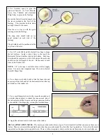
17...Drill a 1/16” hole in the bottom of the fuselage at the
location shown.  Feed the receiver antenna through this hole.
Pull the antenna back to the rear of the fuselage and hold it
in place just in front of the tail skid with a piece of Scotch®
Tape.  Allow the full length of the antenna to trail behind the
model.  Do not cut the antenna to shorten it, as that will
reduce the reception range of your radio.

18...Remove the cabane struts from the die cut plywood
sheet and glue them to the fuselage sides using 5 minute
epoxy.  They should sit on the ledges on the bottom of the
pockets on the side of the fuselage.  When viewed from the
front the cabane struts should be vertical and should not lean
to one side or the other.

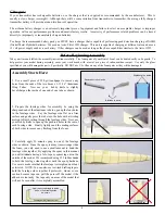
19...Trim the plastic Hatch Cover as shown.  Test fit the
Hatch Cover to the fuselage and adjust as required 
to achieve a proper fit.  Note: A sharp hobby knife and
miniature snips are the best tools for trimming the part.

Remove the paper from the adhesive on one side of the 
velcro squares and apply the two velcro squares to the top of
the fuselage as shown.  Now remove the paper from the
adhesive on the top of the velcro and press the plastic 
Hatch cover into position to attach the velcro to the cover.

Summary of Contents for Bristol Scout

Page 1: ......

Page 2: ...oles in the blades would be plugged and taped over before the next flight By March 1916 the newer Bristol Scout D became the first British fighter to be armed with a synchronised machine gun that could safely fire through the propeller arc This configuration became the favorite mount of British ace Maj James McCudden Soon outdated by more newer designs the Bristol Scout was withdrawn from front li...

Page 3: ...Elevator 1 Bristol Scout Foam Vertical Tail Rudder Fin SIGRPWK294 1 Bristol Scout Top Wing 1 Bristol Scout Bottom Wing 2 Wing Reinforcing Tape Bag 4 SIGRPMGDU293 1 Sig180 Class Power System 2 3 x 10mm Phillips Head Sheet Metal Screws 1 Soft Rubber Prop Shaft Protector Kit Contents Do a complete inventory of your kit before starting assembly Bag 2 SIGRPWB294 1 Bristol Scout Wooden Parts Die Cut She...

Page 4: ...or more channels that will allow you to fly more advanced models in the future Airborne Radio Components We used the HiTEC FEATHER PACK which is a package offered by HiTECH of ultra light airborne components for small electric models like the Bristol Scout Other radio companies may offer a similar package of light weight airborne components The HiTEC FEATHER PACK includes a FEATHER 4 ULTRA LIGHTWE...

Page 5: ... Remove burrs from ends Slight bevel on inside Fuselage Straight Fuselage Bent Fuselage side cross section Apply epoxy sparingly to inside edge of one fuselage side as shown GOOD BAD Assembly Starts Here 1 Use a small piece of 220 grit sandpaper to remove any burrs from the ends of the two 4mm x 3 11 16 Aluminum Wing Tubes Now use your hobby knife to slightly bevel sharpen the inside of one end of...

Page 6: ...f the slot Do the same to both sides of the Vertical Tail NOTE 3 4 wide tape is available at most office supply stores Use only clear tranparent tape Do not use frosted Scotch Magic Tape 6 Use a sharp new hobby knife to trim the foam tabs and excess tape from both ends of the horizontal tail and the top and bottom of the rudder tab 7 Use a small diameter dowel with a smooth rounded end or similar ...

Page 7: ...ly begin to soak up the water Let the paper soak for at least 30 seconds and then carefully SLIDE the paper from the top of the decal DO NOT try to lift the paper from the decal as it will damage the decal Also after the paper is removed DO NOT try to move the decal on the model surface The decal is very thin and fragile If the decal has air bubbles under it use a soft cloth to pat out the bubbles...

Page 8: ...nsmitter on and place the throttle stick in the low position Now plug the airborne battery into the input side of the electronic speed control and the system is operational see NOTICE below Test the system by moving the right stick on the transmitter which should move the rudder and elevator servos Initially the motor is not armed and will not function when you move the throttle stick To arm the m...

Page 9: ... skid with a piece of Scotch Tape Allow the full length of the antenna to trail behind the model Do not cut the antenna to shorten it as that will reduce the reception range of your radio 18 Remove the cabane struts from the die cut plywood sheet and glue them to the fuselage sides using 5 minute epoxy They should sit on the ledges on the bottom of the pockets on the side of the fuselage When view...

Page 10: ...ing checks out securely attach the propeller onto the power system 25 Place the battery in the model and install the Plastic Cockpit Cover Check the balance of the model To do this turn the model upside down and support the model on your finger tips placed 1 2 back from the leading edge of the bottom wing Hold your fingers 20 Pre drill the two motor mount holes in the firewall with a 1 16 drill bi...

Page 11: ... one Wheel Retainer onto each axle and slide it all of the way in as far as possible Now slide on the wheel plastic wheel cover Then install the outer Wheel Retainer Make sure the wheels turn freely 26 Attach the wings on the model using 4 rubber bands 2 for the top wing and 2 for the bottom wing We recommend putting the bottom wing rubber bands on first being carefull to line up the slots in the ...

Page 12: ... and to always fly your model in a safe location and in a safe manner The first test flights should only be made by an experienced R C flyer familiar with high performance R C aircraft JOIN THE AMA The governing body for radio control model airplanes in the United States is the ACADEMY OF MODEL AERONAUTICS commonly called the AMA The AMA SAFETY CODE provides guidelines for the safe operation of R ...

Reviews: