Series 760S/780S UHP Instruction Manual
Appendix A Specifications
IM-76S-78S-UHP
A-3
Page 1: ...HP Instruction Manual Table of Contents IM 76S 78S UHP 0 1 760S 780 UHP Series Insertion Mass Flow Meter Instruction Manual Part Number IM 76S 78S UHP Revision G August 2018 GLOBAL SUPPORT LOCATIONS W...
Page 2: ...21 5879 8521 Fax 8621 5879 8586 COPYRIGHT SIERRA INSTRUMENTS 2017 No part of this publication may be copied or distributed transmitted transcribed stored in a re trieval system or translated into any...
Page 3: ...y Orientation 2 4 Wiring Connections 2 5 Input Power Wiring 2 6 Output Signal Wiring 2 8 Alarm Output Wiring 2 11 Remote Sensor Probe Wiring 2 12 Range Selection Wiring 2 14 Chapter 3 Operating Instru...
Page 4: ...nnections Hazardous Area 2 8 2 10 Load Resistance Versus Input Voltage 2 9 2 11 Isolated 4 20 mA Loop NEMA 4X 2 10 2 12 Non isolated 4 20 mA Loop NEMA 4X 2 10 2 13 Isolated 4 20 mA Loop Hazardous Area...
Page 5: ...60S 780S UHP Instruction Manual Table of Contents IM 76S 78S UHP 0 5 List of Tables 2 1 Pipe Length Requirements for Installation 2 2 3 1 Electronics Validation Results 3 15 3 2 Sensor Validation Resu...
Page 6: ...ctronics device verify the flow meter is not actively monitoring or reporting to any master control system Adjustments to the elec tronics will cause direct changes to flow control settings Caution Al...
Page 7: ...microprocessor based transmitter integrates the functions of flow range adjustment meter validation and diagnos tics in a probe mounted or remotely mounted housing Mass flow rate and totalized flow as...
Page 8: ...sure any spare parts or accessories are not discarded with the packing material Do not return any equipment to the factory without first contacting Sierra Customer Service Technical Assistance If you...
Page 9: ...rature When power is applied to the flow meter the transducer electronics heats the velocity sensor to a constant temperature differential above the gas temperature and measures the cooling effect of...
Page 10: ...Dual Gas Calibration Optional Select one of two factory calibrated flow ranges using a simple ex ternal customer supplied single contact closure User Full Scale Flow Rate Field configure from 50 to 1...
Page 11: ...to 200 feet away The electronics housing may be used indoors or out including wet environments Display options include a 2 x 12 character LCD display of mass flow rate including totalized mass or a s...
Page 12: ...enient access with adequate clearance Also verify the meter is located where the gas is clean and dry and the meter is calibrated for the gas to be measured 4 When using a CSA FM or EEx approved flow...
Page 13: ...pstream of the sensor Upstream Straight Pipe Length Requirements 1 Piping Condition 760S UHP 2 3 8 1 2 inch 760S UHP 3 1 to 6 inch 780S UHP 4 1 to 6 inch Single 90 elbow or T piece 1 D 15 D 1 D Reduct...
Page 14: ...ittings or flanges in the pipeline Fitting components should be blown clean with filtered gas be fore use Mount in a vertical position For horizontal pipelines having a process gas temperature above 3...
Page 15: ...splay board 1 Use a 1 16 inch hex key to loosen the set screw securing the larger end of the enclosure Turn cover counterclockwise and remove 2 Remove 4 screws and standoffs from the display Release t...
Page 16: ...ter enclosure for all wiring con nections The terminal designations are labeled inside the enclosure cover Make sure to observe all CE compliance requirements for AC wiring connections given on the ne...
Page 17: ...All EEx installations must use an approved EEx fitting at both cable entries into the enclosure If conduit seals are used they must be installed with 18 inches of the enclosure The Hazardous Area encl...
Page 18: ...to 4 43 to 5 31 in lbs 0 5 to 0 6 Nm All EEx installations must use an approved EEx fitting at both cable entries into the enclosure If conduit seals are used they must be in stalled within 18 inches...
Page 19: ...C 0 10 VDC optional or a calibrated 4 20 mA output signal This linear output signal represents 0 100 of the flow meter s user full scale DC Output Wiring The 0 5 VDC 0 10 VDC optional signal can drive...
Page 20: ...nce in the loop including the wiring resis tance To calculate Rmax the maximum Rload for the loop use the maximum loop current 20 mA The voltage drop in the loop due to resistance is 20 mA times Rload...
Page 21: ...urrent R load Common 1 2 15 16 Figure 2 12 Non Isolated 4 20 mA Current Loop Connections 1 2 3 4 5 6 7 8 9 10 20 19 18 17 16 15 14 13 12 11 4 20 out 4 20 out R load Current Hazardous Area Enclosures 1...
Page 22: ...at the flow meter s power supply is an acceptable driver voltage for the load connected Take into account that the current used by your alarm loads have to come from the flow meter s power supply In...
Page 23: ...e sensor probe to a remotely mounted flow meter enclosure use only factory supplied cables The electronics sensors and interconnecting cables supplied by Sierra Instruments are calibrated as a complet...
Page 24: ...Enclosure to Sensor Connections NEMA4XEnclosures RED GREEN ORANGE WHITE BLACK Remote enclosure Sensor probe junction box Note S ens or wire color may vary see label in cov er Figure 2 20 Sensor Junct...
Page 25: ...Remote enclosure Note S ens or wire color may vary see label in cov er Figure 2 22 Sensor Junction Box to Remote Enclosure Connections Range Selection Wiring To access range selection connect two wir...
Page 26: ...gle digit LED flashes the revision number of the software in a series of 3 digits followed by the range number The range number continues to flash every three seconds thereafter Record Factory Set Par...
Page 27: ...For units with the optional display you may program the meter without opening the enclosure using the magnetic switches to enter the desired system settings NOTE When activating magnetic switches vari...
Page 28: ...ter model Start Up Screens Password Total Reset To view settings select FUNCTION twice skipping the password To change settings select FUNCTION At the password prompt use the UP arrow until the number...
Page 29: ...n User Full Scale K Factor Range in use Software version shown in series of 3 digits 1 Run Mode Press FUNCTION to view or change settings Use the UP or DOWN button to enter new parameters Press FUNCTI...
Page 30: ...N to enter the high or low alarm setpoint value in engineering units 3 Select FUNCTION to advance to the next option or after 12 seconds of non activity the meter returns to the Run Mode and the new p...
Page 31: ...to the Run Mode and the new K factor is in effect Entering K factor using the Single Digit LED A K factor value of 1 000 VDC means the output value is not af fected and is the factory default setting...
Page 32: ...FUNCTION to advance to the next option or after 12 seconds of non activity the meter returns to the Run Mode and the new UFS is in effect Changing the User Full Scale using the Single Digit LED If the...
Page 33: ...using the Single Digit LED 1 Set the DVM to voltage mode and connect between Vout and Vout on the flow meter terminal block Select the desired range Press the FUNCTION button until a solid 9 appears...
Page 34: ...elect the desired range Select FUNCTION enter the pass word Select FUNCTION again until Total Reset appears on the display 2 Select the UP button and then the DOWN button until the dis play reads Rese...
Page 35: ...10 VDC to 0 0 VDC 1 Set the DVM to voltage mode and connect between Vout and Vout 2 Select FUNCTION enter the password if so equipped Select FUNCTION again until Zero Volts appears on the LCD display...
Page 36: ...LED Adjust UP or DOWN until the DVM indicates between 3 95 and 4 05 mA Set DVM back to voltage mode when adjustment is complete 3 After 12 seconds of non activity the meter returns to the Run Mode and...
Page 37: ...he calibration variables did not drift shift or change values To perform the instrument validation procedures you will need the following equipment certified digital multimeter with minimum 4 characte...
Page 38: ...VDC of the bridge voltage point 7 Record the resulting flow shown on the optional LCD display in Table 3 1 If not using a display or if you prefer to validate one of the analog output signals move the...
Page 39: ...w meter Allow a 6 minute cool down before continuing 3 Remove the cover of the flow meter enclosure to access the sensor connection points Remove the four position jumper from J5 J6 J7 and J8 see belo...
Page 40: ...d resistance values and the Ro and Alpha Ro values from the Calibration Certificate to calculate the tempera ture for each sensor as follows T R R Alpha x R T degrees Celsius R measured sensor resista...
Page 41: ...are no leaks in the line being measured After verifying the factors above follow the troubleshooting proce dures outlined on the next page If you need to return the flow meter to the factory see page...
Page 42: ...gh or low Sensor assembly not aligned correctly to flow Correct alignment with the flow indicator pointing downstream in the direction of flow Flow conditioning plates are not upstream of the sensor C...
Page 43: ...in the data sheet contact Customer Service at 800 866 0200 or 831 373 0200 in the US or 31 0 20 6145810 in Europe Return shipments to USA Headquarters Sierra Instruments Service Department 5 Harris Co...
Page 44: ...Series 760S 780S UHP Instruction Manual Appendix A Specifications IM 76S 78S UHP A 1 Appendix A Product Specifications...
Page 45: ...Appendix A Specifications Series 760S 780S UHP Instruction Manual A 2 IM 76S 78S UHP...
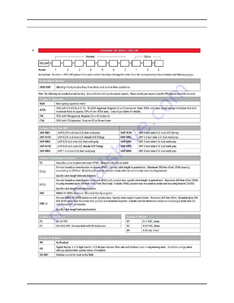
Page 46: ...Series 760S 780S UHP Instruction Manual Appendix A Specifications IM 76S 78S UHP A 3...
Page 47: ...Appendix A Specifications Series 760S 780S UHP Instruction Manual A 4 IM 76S 78S UHP...
Page 48: ...ducts online on Sierra s website Online registration of all of your Sierra products is required for our warranty process Register now at www sierrainstruments com register Lifetime Limited Warranty On...