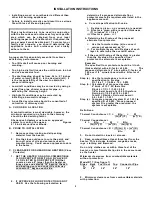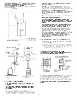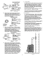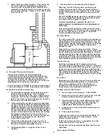
2
These instructions are to be used in conjunction
w ith the fire codes and ordinances for your specific
area which can be obtained from your local
building inspector for Fire M arshall. If required, the
proper perm it m ust be obtained! To protect your
fam ily and property, you should determ ine the
applicable codes and ordinances and strictly
adhere to them .
INSTALLATION INSTRUCTIONS
• Installing a w ood or coral heater is different than
other fuel burning appliances.
• Failure to install correctly could result in a serious
fire w ith loss of life and property.
A proper draft is absolutely essential to achieve
satisfactory perform ance.
• Too little draft w ill cause poor burning and
sm oking.
• Too high a draft w ill cause the unit to burn too hot
and use excessive fuel.
• The draft reading should be from .04 to .07 inches
of w ater colum n (.06 W .C. is the desired draft). It
is the responsibility of the user to obtain the
proper draft range.
• Low draft conditions may be corrected by using a
larger flue pipe, shorter connector pipe, or
extending the chim ney height.
• High draft conditions may be corrected by
installing a barom etric dam per.
• A qualified servicem an should be consulted of
correction of chim ney draft.
A.
CHOOSING A LOCATION
A central location is most desirable, how ever, the
m inim um required run of pipe to the chim ney
should be the deciding factor.
Shenandoah Heaters must use an approved
system for venting flue gases.
Figures
2 - 5 indicate various methods.
B. PRIOR TO INSTALLATION
1.
Rem ove carton, crating and all packing
m aterial from the heater.
2.
Fire the stove outdoors to cure the paint, and
burn off odor of oils and solvents used in
m anufacturing. Could cause unpleasant odors
in the hom e.
C. CLEARANCE FOR SHEANDOAH HEATERS
(Floor
Protector)
1.
SET THE HEATER ON A NON-COM BUSTIBLE
FLOOR PROTECTOR W ITH AN R-VALVE OF
1.0 OR LISTED FLOOR PROTECTION that
covers an area 8” larger than the heater on
three sides and extends 16” beyond the ash
and loading doors and under the chim ney
connector 2” beyond each side.
2.
IF APPROVED FLOOR PROTECTION IS NOT
USED: Use the follow ing calculation to
determ ine if a proposed alternate floor
protector meets the requirem ents listed in the
appliance manual.
a.
Convert specification to R-value.
i. R-value is given – no conversion is needed.
ii. K-factor is given w ith a required thickness
(T) in inches: R = 1/k x T
iii. C-factor is given: r = 1
b. Determ ine the R-value of the proposed
alternate floor protector.
i.
Use the formula in step (a) to convert
values not expressed as ”R”.
ii. For multiple layers, add R-values of each
layer to determ ine the overall R value.
c. If the overall R-value of the system is greater
than the R-value of the specified floor
protector, the alternate is acceptable..
Exam ple:
The specified floor protector should be ¾ inch
thick material w ith a K-factor of 0.84.
The
proposed alternate is 4” brick w ith a C-factor of
1.25 over 1/8” mineral board with a K-factor of
0.29.
Step (a.) Use the form ula above to convert
specification to R-value.
R = 1/k x
T = 1/0.84 x .75 = 0.893
Step (b.) Calculate R of proposed system
4” brick of C= 1.25, therefore
R brick = 1/C = 1/1.25 = 0.80
1/8”m ineral board of k=0.29, therefore
R min.bd = 1/0.29 x0.125 = 0.431
Total R = Rm ineral board =
0.8 + 0.431 = 1.231
Step (c.) Com pare proposed system R of 1.231 to
specified R of 0.893. Since proposed
system R is greater than required, the
system is acceptable.
Definitions:
Therm al Conductance = C = Btu = W
(hr)(ft )( F)
(m )( K)
2
B
2
B
Therm al Conductance =
k = Btu = W = Btu
(hr)(ft )( F)
(m )( K)
(hr)(ft)( F)
2
B
2
B
B
Therm al Conductance = R = (ft )(hr)( F) = (m )( K)
2
B
2
B
Btu
W
3.
Do not install in closets or alcoves.
4.
Keep combustibles at least three feet from the
heater. This includes furniture, magazine racks,
rugs, clothing and firew ood.
Do not dry clothes on or w ithin three feet of the
heater, or store flam m able liquids in the sam e room
as the heater.
M inimum clearances from com bustible materials
w ithout protection:
M odel R77 ( See figure 1)
Sides Back Fuel Door Top Connector Pipe
A B
36" 36" 36" 36" 18"
5.
M inimum clearances from com bustible materials
w ith protection:


