Installation and Startup
Rev 2 Mar.18
23
41110485
Wiring Diagrams
In the following diagrams,
FX30
refers to either FX30 and FX30S.
Always On Installation
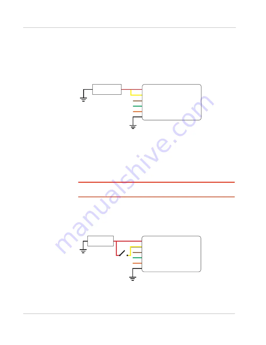
For an Always On application, connect the wires as shown in
.
Figure 2-15: Always on installation
•
Pin 1 (Power)—Use the red wire in the DC cable to connect Pin 1 to the
power source.
•
Pin 2 (Ground)—Use the black wire in the DC cable to connect Pin 2 to
ground. See also
Step 2—Mount and Ground the FX30S Chassis
•
Pin 3 (On/Off)—Connected to power
•
Optional—I/O 1, I/O 2, and I/O 3
Note: See
Table 3-10, WP8548 Radio Module Interface Mapping,
on page 59 for the radio
module GPIO and Linux interface mapping of pin 3, I/O 1, I/O 2, and I/O 3.
On/Off Installation
For an On/Off application, connect the wires as shown in
or
Figure 2-16: On/Off Installation with switch
•
Pin 1 (Power)—Use the red wire in the DC cable to connect Pin 1 to the
power source.
Gateway
Power
On/Off
Ground
DC power source
1
3
2
I/O1
I/O2
I/O3
FX30
DC power source
2 Ground
I/O 3
I/O 2
I/O 1
1 Power
3 On/Off
On/Off switch
DC power source
Gateway
Power
On/Off
Ground
1
3
2
I/O1
I/O2
I/O3
FX30
DC power source
2 Ground
I/O 3
I/O 2
I/O 1
1 Power
3 On/Off
On/Off switch


