


Rev 2 Feb.16
13
Specifications subject to change
4
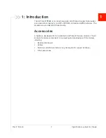
4: Routing Constraints and Recommen-
dations
This section describes general routing constraints and recommendations for the
AirPrime WP8548 module.
Note: This is a non-exhaustive list of suggested design guidelines. The developer is
responsible for deciding whether to implement these guidelines.
General Rules and Recommendations
Clock and other high-frequency digital signals (e.g. serial buses) should be routed
as far as possible from the module’s analog signals.
If the application design makes it possible, all analog signals should be separated
from digital signals by a ground trace on the PCB.
Tip:
Avoid routing any signals under the module on the application board.
PCB Layout Recommendations
Ground pads should be re-flowed on to the host PCB with < 30% voiding to allow
effective heat dissipation.
Power Supply
When designing the power supply, make sure that VBAT_BB / VBAT_RF meet the
requirements listed in the WP8548 Product Technical Specification.
Careful attention should be paid to the following:
•
Power supply quality — PFM, or PSM systems should be avoided; Low ripple,
linear regulation or PWM converters are preferred for low noise.
•
Capacity to deliver high current peaks in a short time (for pulsed radio
emission)
•
VBAT_BB / VBAT_RF must support peak currents with an acceptable voltage
drop that guarantees the minimum required VBAT_BB / VBAT_RF value.
•
VBAT_BB / VBAT_RF signal pads must never exceed the maximum required
VBAT_BB / VBAT_RF value, otherwise the module’s power amplifier and GPS
chipset may be severely damaged.
•
A weakly-designed (not robust) power supply could affect EMC performance,
the emission spectrum, and the phase error and frequency error.
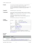
Summary of Contents for AirPrime WP8548
Page 1: ...AirPrime WP8548 Hardware Integration Guide 4118723 Rev 2 ...
Page 2: ......
Page 8: ...Hardware Integration Guide Specifications subject to change 8 4118723 ...
Page 10: ...Hardware Integration Guide Specifications subject to change 10 4118723 ...
Page 20: ...Hardware Integration Guide Specifications subject to change 20 4118723 ...
Page 24: ...Hardware Integration Guide Specifications subject to change 24 4118723 ...
Page 25: ......
Page 26: ......