41110461XXXX
Rev 0.12
January 16, 2017
16
Hardware Integration Guide
Introduction
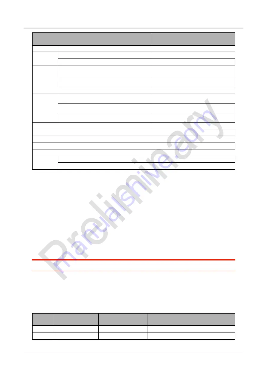
Parameter/Feature
Value
QZSS
L1
Satellite
channels
Tracking
40
Acquisition
118
Standalone
Time To
First Fix
(TTFF)
1,2,4,6
Hot start:
1 s
Warm start
27 s
Cold start
29 s
Sensitivity
(GPS,
GLONASS,
BeiDou)
Tracking
4,5,6
-163 dBm
Cold start Acquisition
-158 dBm
Hot start Acquisition
-145 dBm
Horizontal Position accuracy
1,3,4,5,6,
2 / 5
7
Altitude accuracy
1,3,4,5,6,
4 / 10
7
Velocity accuracy
1,3,4,5,6
0.1
Tracking update rates
1 Hz
SBAS support
3
WAAS, EGNOS, MSAS,GAGAN
Message
Protocol
NMEA 0183 Version
V3.0
Supported Sentences
GSV, GNS, GSA, GGA, GRS, RMC, VTG
1 Open sky, all SV RF signal level = -130dBm, Number of GPS SVs > 6, Number of Glonass SVs>5, Number of Galileo
SVs>5, Number of BeiDou SVs>5
2 TTFF values show results in worst conditions (as an external host user): timing measurement start when GPS control
request is sent on AT command interface and stop when NMEA frames (1Hz update) display 2D fix information.
3 Scenarios used for accuracy measurements simulate car travel including direction, altitude and speed variations.
4 The performance are obtained by using external Pre-SAW and LNA for conducted test setup at Room temperature, it is
used to simulate the active antenna
as customer’s application.
5 1Hz Navigation used for all tracking/navigation tests.
6 GNSS constellations used: GPS + G G Beidou
7 Accuracy data are provided Circular Error Probable, CEP-50 / CEP-95. Means that 50%/95% of the positions returned
calculated have an error lower or equal to the accuracy value.
8 Tracking sensitivity is the lowest GNSS signal level for which the device can still detect an in-view satellite 50% of the
time when in sequential tracking mode..
9 Acquisition sensitivity is the lowest GNSS signal level for which the device can still detect an in-view satellite 50% of the
time.
Note:
All GNSS characterization data are measured in conducted RF path with GNSS simulator at room
temperature.
1.4.2.
GNSS Antenna Interface
The GNSS Antenna Interface is defined in the table below.
Table 15.
GNSS Antenna Interface Pads
Pad
Name
Direction
Function
BA4
GND
GNSS Antenna Ground
BA5
GNSS_ANT
Input
GNSS Antenna Interface


