Installation and Startup
Rev 4 Jan.15
43
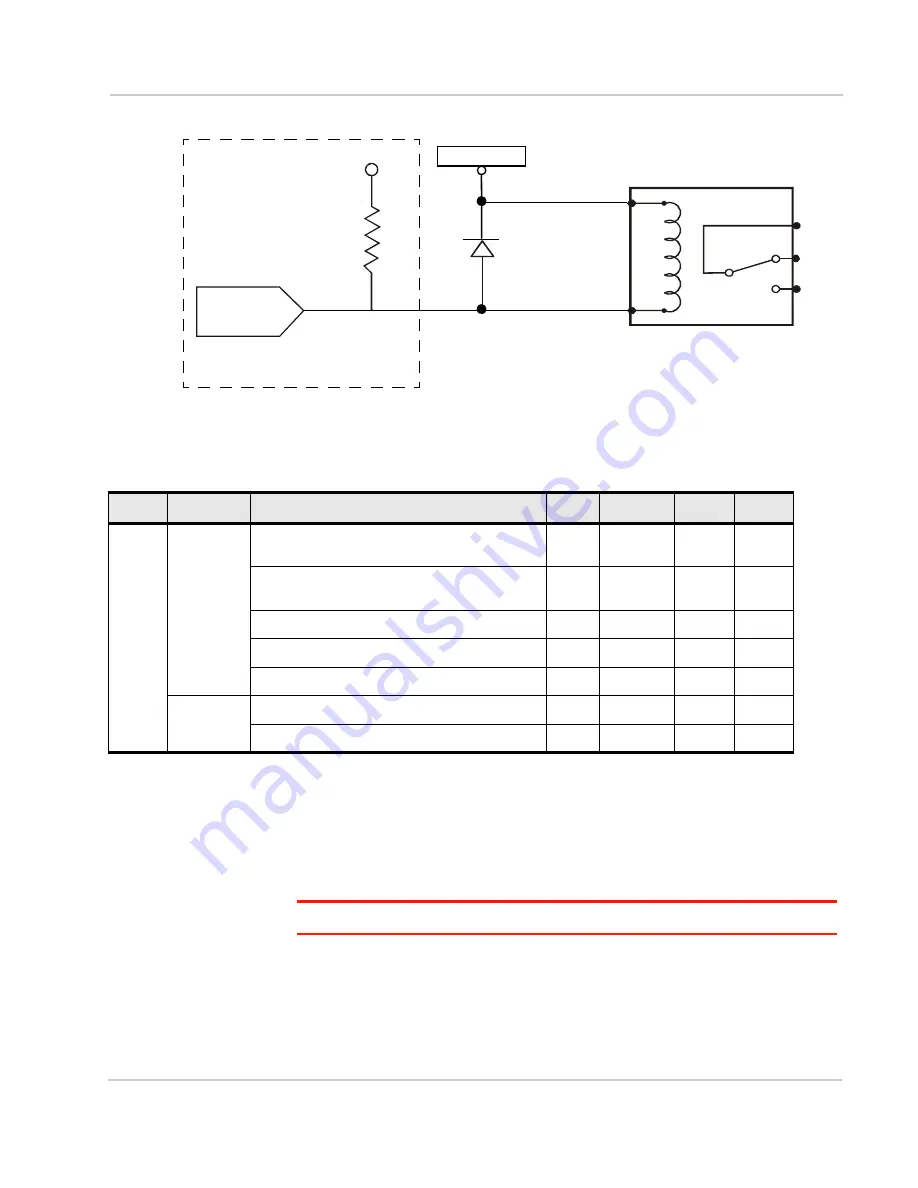
Figure 2-26: Digital Output Operation
I/O X-Card Digital I/O Input Pins
Pins 3, 4, 11 and 12 are programmed in ACEmanager to monitor inputs, respond
to certain types of events or trigger a digital output. They behave exactly like the
Digital I/O (pin 4) on the power connector as described in
Note: Digital Input 1 in ACEmanager is reserved for Pin 4 on the power connector.
Pins 3, 4, 11 and 12 (Digital inputs 2 to 5) have a voltage of 3.3 VDC when set to
high in ACEmanager. A voltage on the pins of:
•
2.2 VDC to 30 VDC = logic 1
•
0 VDC to 1.3 VDC= logic 0
2.8 V
51 k
internal
pull up
Voltage supply
CL+
CL-
COM
NC
NO
I/O Circuit
Pins 3, 4, 11, and 12 are normally at 2.8 V,
External Relay Circuit
(Exact voltages and configuration
depend on the actual system design.)
AirLink GX device
Flyback diode
but pulled low when activated
Table 2-6: Digital I/O
Pins
Name
Specification
Min
Typical
Max
Units
3
4
11
12
DIO[2...5]
(as input)
Input low state voltage
(At or below this voltage, relay reads as low)
—
—
1.2
V
Input high state voltage range
(At or above this voltage, relay reads as high)
2.2
—
—
V
Input leakage current at 5 V
—
0.05
—
mA
Input leakage current at 12 V
—
1.8
—
mA
Input leakage current at 24 V
—
5.5
—
mA
DIO[2...5]
(as output)
Open drain drive to ground
—
100
—
mA
Maximum open circuit voltage applied
—
—
30
V
Summary of Contents for Airlink GX450
Page 1: ...AirLink GX Series Hardware User Guide 4114008 Rev 4...
Page 2: ......
Page 6: ...AirLink GX Series Hardware User Guide 6 4114008...
Page 62: ...AirLink GX Series Hardware User Guide 62 4114008...
Page 68: ...AirLink GX Series Hardware User Guide 68 4114008...
Page 71: ......
Page 72: ......


