background image


CIM Door Upgrade 

Page 20 

IP-0021 

Step 

Procedure 


8.   

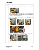
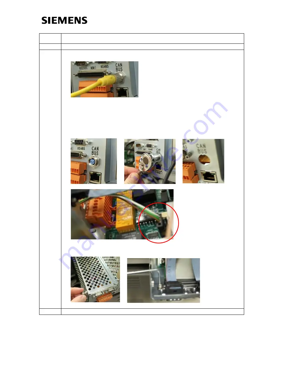
(Use this step if CAN connector is located on the front of the SYSCON cage 
and is in use with a connected cable) 


In cases WHERE the CAN connector is in use (connected to a CAN Extension 
Unit), the connector must be moved as described below in order to prevent the 
connector from pressing against the CIM.  
 
A) Remove the cable (unscrew silver sleeve). Then, remove the plug from the 
cage by unscrewing the nut using a 14mm wrench. Unplug the CAN plug cable 
from the SYSCON board.  


B) Remove the side panel from the cage by loosening the thumbscrews. Then, 
remove the HMI connector using a hex wrench (size 3/32”). 


Summary of Contents for SYSCON+

Page 1: ...culty Level Medium Estimated time to execute 2 Hours Revision History Issue Date Reason 00A 8 18 12 Beta Draft 001 8 20 12 First Revision 002 8 28 12 Changes based on review 003 8 29 12 Minor Change 004 10 11 12 Changes based on beta results 005 12 13 12 Change error in image Break out sections 006 11 11 13 Update to include Maxum I 007 1 24 14 Update for CIM cover ...

Page 2: ...utilizes a much larger display area and provides enhanced graphics and on screen help functions In addition to the enhanced user display the CIM door contains the CIM electronics modules used to control the display The CIM electronics are capable of performing several functions within the Maxum including being the processor for a Modular Oven Configuration Maxum II This procedure involves installa...

Page 3: ...asic steps for completing this procedure are as follows Refer to the diagrams on the following pages 1 Install Gas Chromatograph Portal workstation software version 5 10 and System Manager software version 5 0 19 if not already installed 2 Upgrade the analyzer to Release 4 40 and the SYSCON OS and Boot firmware if not already installed 3 Modify analyzer IP addresses to support the retrofit 4 Power...

Page 4: ... 4 IP 0021 SYSCON1 External Ethernet or internally mounted Ethernet device Internal Ethernet SYSCON1 CIM CAC3 CIM Touch Screen Color Display Door Figure 3 Diagram of Ethernet and User Display Connections Final Configuration ...

Page 5: ...rew drivers is required to perform this procedure Warning Full safety precautions must be followed throughout all sections of this procedure to prevent possible injury equipment damage or death Verify that the area is clear of flammable gases and vapors and that appropriate authorization is obtained to do the work hot work permits A retrofit kit is required for this procedure Due to different door...

Page 6: ...internal EC past its thermal limit In order to accommodate the upgrade to a CIM Door the ambient temperature needs to be low enough to keep the internal temperature of the electronics enclosure below 60 C before installation of the CIM Door For this reason not all analyzers may be a good candidate for upgrading to the CIM door To determine if a particular analyzer is a good candidate perform the f...

Page 7: ...IM and SYSCON Figure 4 SYSCON Board Connections Internal Bus CAN Direct 1 CAN Direct 2 CAN Direct 3 CAN Direct 4 CAN Direct 5 AT Bus PCI Slot 1 PCI Slot 2 PCI Slot 3 PCI Slot 4 10BaseT I O Terminal Blocks Maintenance Panel Display SIMM 72 SIMM 80 2 Flash SRAM SIMM 80 1 RS 232 488 Not Used Not Used SYSCON Debug Power Reset CAN Bus Purge 10Base2 ...

Page 8: ...Controller X05 Analog Digital Inputs X06 CAN Bus Connector X07 Ethernet 10Base T X08 Communication Board NetCom or Ethernet to Fiber Optic Converter Slot 1 X09 not used X10 Analog and Digital I O Board X11 Analog and Digital I O Board X12 10BaseT Ethernet Board Figure 5 SYSCON1 Cage Connections Original Assembly Newer Assembly ...

Page 9: ...CIM Door Upgrade Page 9 IP 0021 SYSCON1 Figure 6 CIM Board Connections ...

Page 10: ...tallation disk The installation program should launch automatically 2 From the menu select the System Manager Setup Wizard 3 Following the instructions on the screen use the Setup Wizard to upgrade the System Manager Software to the required version 5 0 19 4 After System Manager is upgraded select the GCP Setup Wizard from the installation menu in order to upgrade the Gas Chromatograph Portal Soft...

Page 11: ...f GCP refer to the Getting Started Manual for GCP part number A5E03944542001 1 To upgrade open the GCP Network portal and choose the correct analyzer Then choose the Software Upgrade button at the top of the window After logging in a window similar to the window below is displayed If all applications are not already in hold then place them in hold at this time using the Hold all Applications butto...

Page 12: ...grade will be displayed Monitor for any errors Note At one point during the upgrade a DBConverter window will pop up This is an automatic function of the upgrade script No user intervention is necessary 3 When the upgrade is finished the following message should be displayed Click OK to continue Note that if the above window is not displayed then the upgrade may not have completed successfully ...

Page 13: ... with the device after the upgrade Note This section requires use of the Gas Chromatograph Portal GCP software For additional information relating to use of GCP refer to the Getting Started Manual for GCP part number A5E03944542001 This section also requires use of the HMI emulator Since the software was upgraded this will be the new emulator that looks the same as the CIM Display More information...

Page 14: ...CIM Door Upgrade Page 14 IP 0021 SYSCON1 ...

Page 15: ...oftkey This will bring up the following window Enter the numbers exactly as shown above and then click OK These are settings that will be required to communicate with the CIM via internal IP bus 6 Once the IP addresses have been changed close the HMI emulator and the GCP connection Note that depending on the configuration and timing the software may freeze for several seconds while waiting for net...

Page 16: ...e cover aside until the procedure is complete 2 Using appropriate safety precautions power down the analyzer 3 After appropriate safety precautions have been followed open the door to the Electronics Enclosure EC 4 Disconnect the HMI cable from SYSCON cage by loosening the fastening screws and then pulling the connector out Also disconnect the HMI cable from any clips that affix the cable to the E...

Page 17: ...CIM Door Upgrade Page 17 IP 0021 SYSCON1 ...

Page 18: ...ont of the SYSCON cage may bump against the CIM hardware preventing the door from closing Changes may need to be made in order for all hardware to have the correct clearance 6 User installed wiring going to the orange I O connectors on the front of the SYSCON cage must be dressed in such a way that they do not prevent the door from closing This means that the wires should bend at a right angle clo...

Page 19: ...e configuration 7 Use this step if CAN connector is located on the front of the SYSCON cage and is equipped with a bus termination plug In many cases the CAN connector will not be in use and will be equipped with a terminator plug If this is the case use this step to move the connector so that it will not contact the CIM If the connector is in use with a cable attached refer to step 7 A Remove the...

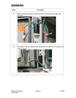
Page 20: ...o a CAN Extension Unit the connector must be moved as described below in order to prevent the connector from pressing against the CIM A Remove the cable unscrew silver sleeve Then remove the plug from the cage by unscrewing the nut using a 14mm wrench Unplug the CAN plug cable from the SYSCON board B Remove the side panel from the cage by loosening the thumbscrews Then remove the HMI connector usi...

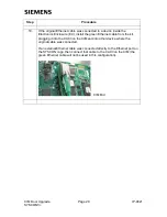
Page 21: ... blue connector clips and pulling D Feed the flat part of the CAN connector cable through the HMI connector hole Plug the cable in to the SYSCON board in the same location that it was plugged in previously E Replace the side panel of the cage and secure using the thumb screws Then secure the connector to the inside of the cage with a cable tie as shown ...

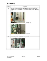
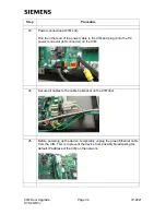
Page 22: ...rade Page 22 IP 0021 SYSCON1 Step Procedure 9 Remove the ground lugs from the door end These will be reused on the new door 10 If equipped remove the HMI to EC ground wire at the EC end This wire will not be reused ...

Page 23: ...CIM Door Upgrade Page 23 IP 0021 SYSCON1 Step Procedure 11 Remove door by lifting off hinges 12 Install new door onto hinges ...

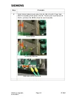
Page 24: ...CIM Door Upgrade Page 24 IP 0021 SYSCON1 Step Procedure 13 Remove the purge cable running from the SYSCON to the PECM SYSCON End PECM End PECM2 shown PECM1 has similar location ...

Page 25: ...g to the SYSCON see below This is a purge bypass cable used to disable the purge alarm If this is installed it should remain installed in the same location The SYSCON end of the Y shaped cable will plug into the bypass cable 14 On the new CIM verify that the switch settings are correct CPLD Spare switches should all be Off down The I2 C Bus Pull Up switches should all be On to the left ...

Page 26: ...CIM Door Upgrade Page 26 IP 0021 SYSCON1 Step Procedure 15 Connect Y shaped purge cable from PECM to both CIM and SYSCON CIM End PECM End SYSCON End ...

Page 27: ... the front of the SYSCON cage This may be a directly connected external cable or it may be connected to another device such as a fiber converter board inside the Electronics Enclosure EC If the cable is connected to a device in the EC disconnect it at both ends 17 Install the short gray Ethernet cable from the kit plugging it into the RJ 45 Ethernet port on the front of the SYSCON cage and the RJ ...

Page 28: ...nstall the green Ethernet cable from the kit plugging it into the CAC3 on the CIM and into other device where the original cable was connected If an external Ethernet cable was connected directly to the Ethernet port on the SYSCON cage then connect that cable to the CAC3 on the CIM the green Ethernet cable will not be used in this configuration CIM End ...

Page 29: ...ON1 Step Procedure 19 Install the serial cable from the SYSCON Debug Port on the front of the SYSCON cage to Serial Port 1 on the CIM Base board not the CIM debug port SYSCON End CIM End 20 Connect the ground clips from the door to the EC ...

Page 30: ...1 Install Intrinsic Safety ground wires from the CIM to the EC These must attach to separate ground posts in the EC The two posts near the back of the EC just above the PECM should be used if possible Ground posts IS Grounds Attached CIM IS Ground Connections ...

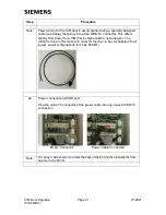
Page 31: ...r a CIM that is shipped with a new analyzer The retrofit is done in this manner in order for the door to be compatible with all legacy power configurations such as PECM1 22 Power connection at WDB end Plug the white I2 C connector of the power cable into any unused WDB I2 C connection Empty Connector Power Cable Connected Note The power cable should run across the back of the EC and then towards t...

Page 32: ...he CIM and plug it into the P2 power connector left connector on the CIM 24 Secure all cables to the cable tie bracket on the CIM door 25 Before powering up the device temporarily unplug the green Ethernet cable from the CIM This is to prevent the device from possibly broadcasting the default IP address of the CIM on the network ...

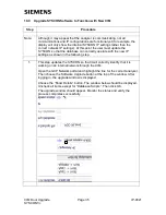
Page 33: ...stem will proceed with a list of questions Read each question carefully and follow the instructions to questions on the screen to change the IP settings These are the customer specific IP settings that were set for the SYSCON before the SYSCON IP settings were changed Note At this time only change the IP Address the Subnet Mask if different and the Default Gateway Address Note that if the Default ...

Page 34: ...ON1 Step Procedure 6 Now that the IP settings for the CIM are correct plug the green Ethernet cable back into the CIM 7 Allow the analyzer to reboot and allow it to come up 8 Using a hex wrench replace the protective cover on the CIM board ...

Page 35: ...e can correctly operate with the new IP settings as shown in the following step 1 This step updates the SYSCON so that it will correctly identify that it is working on an internal network through the CIM Open the GCP Network portal and highlight the line for the correct analyzer Then choose the Software Upgrade button at the top of the window After logging in the upgrade window is displayed Choose...

Page 36: ...the right side of the screen Access the context sensitive Help but touching the help icon on the upper right corner of the CIM display Then touch another item on the screen such as a menu selection A dialog box should appear that displays information about the item Verify the IP addresses for the analyzer This can be done by choosing the icon labeled Configure on the lower right hand side of the s...

Page 37: ...isplay connects to analyzer but time does not update Database is not operating correctly possibly because the upgrade to version 4 40 did not complete successfully Verify that the database is at the correct version Contact Customer Support for assistance No communication to analyzer on network 1 Ethernet cable from CIM to ESB not plugged in correctly or is faulty 2 IP address for the CIM not set c...

Page 38: ...problem seen and whether the replacement procedure was completed For this reason some steps below may not be applicable If assistance is needed it is advisable that Siemens support be contacted prior to fallback 1 Using appropriate safety precautions power down the analyzer 2 Open the door and disconnect all cables from the CIM door This includes the following 1 The power cable running to the CIM ...

Page 39: ...g port on the SYSCON requires a computer running a terminal communication program such as Hyperterminal Only qualified users should attempt this without assistance Contact Siemens support for more information if assistance is needed 5 Apply power to the analyzer The boot sequence should appear on the HMI 6 Important If the step to modify database scripts as seen on page 35 has been attempted then ...

Page 40: ...indow should be displayed as described previously in the procedure refer to page 35 Uncheck all items except for Convert Existing Database and Database Scripts Then click OK The upgrade window should appear Monitor the status and verify the process completes successfully 10 Verify that the purge alarm LED and all other LEDs work as expected 11 Verify that the Maintenance Panel display works as exp...

Page 41: ...M Display In addition the display emulator in the workstation software is referred to as the HMI emulator The HMI software on the CIM utilizes interactive display screens menus and icons for common functions In addition the software is equipped with context sensitive help for most functions This makes the device intuitive and simple to use once the user is familiar with the basic operation A PC ba...

Page 42: ...CIM Door Upgrade 42 IP 0020 SYSCON2 ...

Page 43: ...en indicate the analyzer system status and work the same as for the original Maintenance Panel These LEDs are physically attached to the color display although they are controlled by a separate control cable from the CIM Board Green Power LED Yellow Warning LED Red Fault LED Red Purge LED The green Power LED lights when the power supply is on The yellow Warning LED lights when the Maintenance requ...

Page 44: ...go back to a previous menu screen or launch the interactive help function all denoted by easy to understand icons The help function on the main navigation bar is an interactive feature that provides context sensitive assistance It is accessed by clicking the help icon on the far upper right and then clicking the area of the screen for which help is desired When the feature is used a small pop up w...

Page 45: ...ser to navigate directly to commonly used screens This includes access to the alarm screen as well as settings for valves temperature pressure and streams It also allows the user to easily navigate to the different menu levels monitor maintenance and configure The softkey bar appears at the lower edge of the screen Its gray background distinguishes it from the content area The softkey bar associat...

Page 46: ... tool bar icons The three options show up any time one of the main three menus is displayed Select the Home icon in the far upper right corner of the CIM Display in order to display the default menu which will display the menu icons The toolbar is a new feature created for the CIM display that allows the user to navigate directly to commonly used screens In addition to selections described above t...

Page 47: ...function of the CIM Display eliminates the need for this When data entry is required on the physical CIM Display a pop up window with numeric keypad appears on the screen as shown below Figure 3 3 Window for Data Entry on CIM Display When the HMI emulator is used the data entry window does not appear because the numeric keys on the computer keyboard can be used Entry of Data ...

Page 48: ... if using the emulator This puts the software in an interactive help mode This mode is denoted by the background for the help icon changing color The help mode is context sensitive This means that for the next item you touch or click the software will display a help window for that item In the figure below the help icon was selected and then the Temp icon on the toolbar This displayed the help tex...

Page 49: ...The background of the help icon will change color when in interactive help mode To see help for an alarm click the Description field for that alarm while in interactive help mode This will display the alarm help screen In the figure below the help icon was selected and then the Description field for the first alarm on the list This displayed the help text window in the middle of the screen Figure ...

Page 50: ...set see description of SET TIME softkey below To see if you are authorized to perform a specific function use the appropriate menu path to navigate to that function If the following screen appears then password entry is necessary to perform that function i e the current level of access is not sufficient to perform the function Select the LOGIN softkey and then enter the appropriate password and pr...

Page 51: ...hese are public operate calibrate maintain configure and super The default access level for each of these users matches their names In addition multiple individual users may be defined These users must have unique names and they can be created with either operate calibrate maintain or configure access levels Creation and deletion of users must be performed using the workstation software Refer to t...

Page 52: ...same time Hints It is important that sensors be matched to each other to prevent variations in tolerance from affecting the measurement If possible it is recommended that the analyzer remain powered up while placing the sensors This will save time in stabilizing the internal temperature All sensors must be placed so that the sensor cannot touch any surface Procedure Step 1 Place a temperature sens...

Page 53: ...sure all 4 temperatures Take the average of the three internal temperatures Step 5 f the difference between the internal EC temperature and the external ambient is greater than 10 C then the maximum allowed ambient temperature is likely to be affected by the addition of a CIM Door To accommodate a CIM Door the ambient temperature needs to be low enough to keep the internal temperature of the elect...

Reviews: