7PG2113/4/5/6 Solkor Description of Operation
©2010 Siemens Protection Devices Limited Chapter 1 Page 80 of 80
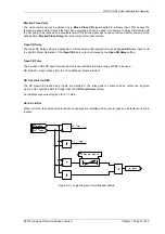
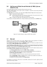
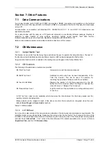
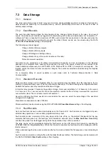
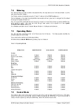
Control Mode commands are password protected using the Control Password function – see Section 6.9.
7.7
Real Time Clock
Time and date can be set either via the relay fascia using appropriate commands in the System Config menu or
via the data comms channel(s). Time and date are maintained while the relay is de-energised by a back up
storage capacitor.
In order to maintain synchronism within a substation, the relay can be synchronised to the nearest second or
minute using the communications interface, or a binary input.
The default date is set at 01/01/2000 deliberately to indicate the date has not yet been set. When editing the
Time
, only the hours and minutes can be edited. When the user presses
ENTER
after editing the seconds are
zeroed and the clock begins running.
7.7.1 Time Synchronisation – Data Communication Interface
Where the data comms channel(s) is connected the relay can be directly time synchronised using the global time
synchronisation. This can be from a dedicated substation automation system or from ‘Reydisp Evolution’
communications support software.
7.7.2 Time Synchronisation – Binary Input
A binary input can be mapped
Clock Sync from BI
. The seconds or minutes will be rounded up or down to the
nearest vale when the BI is energised. This input is leading edge triggered.
7.8
Settings Groups
The relay provides four groups of settings – Group number (Gn) 1 to 4. At any one time only one group of settings
can be ‘active’ – SYSTEM CONFIG>
Active Group
setting.
It is possible to edit one group while the relay operates in accordance with settings from another ‘active’ group
using the
View/Edit Group
setting.
Some settings are independent of the active group setting i.e. they apply to all settings groups. This is indicated
on the top line of the relay LCD – where only the
Active Group No
. is identified. Where settings are group
dependent this is indicated on the top line of the LCD by both the
Active Group No
. and the
View Group No
.
being displayed.
A change of settings group can be achieved either locally at the relay fascia, remotely over the data comms
channel(s) or via a binary input. When using a binary input an alternative settings group is selected only whilst the
input is energised (
Select Grp Mode: Level triggered
) or latches into the selected group after energisation of the
input (
Select Grp Mode: Edge triggered
).
Settings are stored in non-volatile memory.
7.9
Password Feature
The relay incorporates two levels of password protection – one for settings, the other for control functions.
The programmable password feature enables the user to enter a 4 character alpha numeric code to secure
access to the relay functions. The relay is supplied with the passwords set to
NONE
, i.e. the password feature is
disabled. The password must be entered twice as a security measure against accidental changes. Once a
password has been entered then it will be required thereafter to change settings or initiate control commands.
Passwords can be de-activated by using the password to gain access and by entering the password
NONE
.
Again this must be entered twice to de-activate the security system.
As soon as the user attempts to change a setting or initiate control the password is requested before any changes
are allowed. Once the password has been validated, the user is ‘logged on’ and any further changes can be
made without re-entering the password. If no more changes are made within 1 hour then the user will
automatically be ‘logged off’, re-enabling the password feature.
The Settings Password prevents unauthorised changes to settings from the front fascia or over the data comms
channel(s). The Control Password prevents unauthorised operation of controls in the relay Control Menu from the
front fascia.
The password validation screen also displays a numerical code. If the password is lost or forgotten, this code
should be communicated to Siemens Protection Devices Ltd. and the password can be retrieved.


