


Document Number: 129-369
Installation Instructions
September 30, 2002
Wiring
CAUTION:
Use care when removing the knockout.
Do not damage the circuit board.
Do not use autotransformers. Use earth ground
isolating step-down Class 2 transformers.
Determine supply transformer rating by summing total
VA of all actuators used. The maximum rating for a
Class 2 power supply circuit is 100 VA.
Actuator
Power
Consumption
Actuators per
Class 2 supply circuit*
(80% of transformer VA)
SKD62UA
17 VA
4
* Operating more actuators requires additional
transformers or separate 100 VA power supplies.
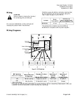
Wiring Diagrams
EA1077R1
LED Status
Indication
Stroke Calibration
Rotary Switches
LO and UP
Connection
Terminals
G0
AC 24V
50/60Hz
0 ... 10V
4 ... 20mA
G
G0
Chm
G Y M U Z
OK
Green
Status
Calib.
Red
Calib.
Error
Valve
Jam
1 2 3 4
Figure 9. DIP Switches.
DIP Switches
(From Left to Right)
1
Select Direction
of Operation
2
Sequence Control
or
Stroke Limit Control
3
Selection of
Control
Signal
4
Selection of
Flow
Characteristic
ON
Reverse-acting
Sequence control
4 to 20 mA
Modified*
OFF
(Factory Settings)
Direct-acting
Stroke limit control
0 to 10 Vdc
Default
*Changing the default setting will modify an equal percentage valve to a linear flow characteristic. When set
to default, the flow characteristic is determined by the valve body.
Calib.
Status
Siemens Building Technologies, Inc.
Page 3 of 6