


Operation
6.4 Digital display
SITRANS P300 with HART communication
6-8
Operating Instructions, 06/2005, A5E00359579-02
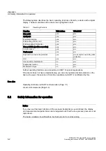
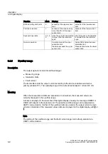
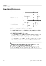
Function
Mode
Display
Display
Blind adjusting limit point
6
exceeds of the upper sensor
limit
exceeds of the lower sensor
limit
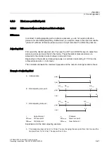
Position correction
7
exceeds of the max. span by
more than 5% of the upper
current limit
exceeds of the lower current
limit
Keyboard operation
2, 3, 5,
6
when the span to be adjusted
is larger than the maximum
span
when the span to be adjusted
is smaller than the minimum
span
Normal operation
Current exceeds the upper
saturation limit
Pressure exceeds the upper
sensor limit.
Current falls below the lower
saturation limit
Pressure falls below the lower
sensor limit.
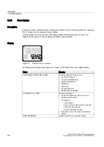
6.4.6
Overflow range
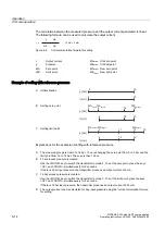
Description
The output signal is divided into defined ranges:
•
Measuring range
•
Saturation limits
•
Fault current
The transmitter emits the output current according to the device variables selected as
primary variable (PV). The operating range of the current lies between 4 mA and 20 mA.
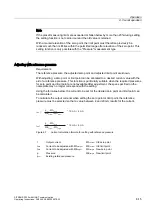
Meaning
When the measurement limits are exceeded or not reached, the measured values are
correctly displayed in the overflow range.
A ticker is displayed in the lower line of the digital display showing the message UNDER or
OVER with respect to the selected unit. The possible overflow range can be adjusted via
HART communication. If either of the overflow limits are violated, the output current remain
constant. Violations of the measured value limits are displayed on the digital display with or
.
Note
The setting of the overflow range and the fault current range can be freely selected via
HART communication.


