background image


    Operating instruction
 

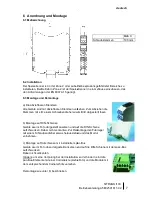
6  Arrangement and fitting 

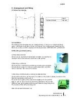
6.1 Dimension drawing 

 
6.2 Installation 

The isolating power Supplies may be installed in Zone 2, Zone 22 or outside hazardous 
areas. In the case of operation in Zone 2 or Zone 22, the isolating power Supply must be 
fitted in an enclosure which complies with the requirements of EN 60079


6.3 Mounting and dismounting 


a) Detachable terminals 

All devices are provided with detachable terminals. A screwdriver is 
needed to remove the terminals (as shown in the picture).


b) Mounting on DIN rails  

Set the device on the DIN rail and tilt/snap onto the rail as depicted. 
Do not set at an angle. For removal, pull the base latch out a little 
with a screwdriver and remove the module. 


c) Mounting on DIN rails with an already-installed pac

As depicted in the photo, set the device in position on the pac
DIN rail) and tilt/snap until it locks in.  
Do not tilt at an angle to either side when snapping onto the pac

Note: In order to prevent pole reversal during installation, the pac
elements have been equipped with a keyed connection plug (see photo). 
The module is fitted with a matching slot. 

 
Dismount as described below in b). 


english 


                        SITRANS I100 

15


Operating instruction A5E02591611-02 


The isolating power Supplies may be installed in Zone 2, Zone 22 or outside hazardous 
areas. In the case of operation in Zone 2 or Zone 22, the isolating power Supply must be 
fitted in an enclosure which complies with the requirements of EN 60079-15 or EN 61241-1  

All devices are provided with detachable terminals. A screwdriver is 
needed to remove the terminals (as shown in the picture).


tilt/snap onto the rail as depicted. 

Do not set at an angle. For removal, pull the base latch out a little 

installed pac-Bus 

sition on the pac-Bus (already mounted on the 

Do not tilt at an angle to either side when snapping onto the pac-Bus. 

: In order to prevent pole reversal during installation, the pac-Bus 

equipped with a keyed connection plug (see photo). 


Size X 

Screw terminals 

108 mm 


Summary of Contents for SITRANS I100 7NG4124-0AA00

Page 1: ...Betriebsanleitung Operating instruction Speisetrenner HART Isolating power Supply leitung Operating instruction 03 2010 Isolating power Supply HART SITRANS I100 7NG4124 0AA00 ...

Page 2: ...ltung 10 10 Zubehör und Ersatzteile 10 11 Zertifikate und weitere Dokumentation 10 Content 1 Safety instructions 11 2 Conformity to standards 11 3 Function 12 4 Marking and technical data 12 5 Engineering 13 5 1 Max ambient temperatures 13 5 2 Power dissipation 13 5 3 Engineering of the power dissipation in cabinets 14 6 Arrangement and fitting 15 6 1 Dimension drawing 15 6 2 Installation 15 6 3 M...

Page 3: ...ngeschlossen werden Der Speisetrenner darf nur an Geräte angeschlossen werden in denen keine höheren Spannungen als AC 253 V 50 Hz auftreten können Die sicherheitstechnischen Werte der des angeschlossenen Feldgeräte s müssen mit den Angaben des Datenblattes bzw der EG Baumusterprüfbescheinigung übereinstimmen Bei Zusammenschaltungen mehrerer aktiver Betriebsmittel in einem eigensicheren Stromkreis...

Page 4: ...itstechnische Daten max Spannung Uo max Strom Io max Leistung Po innere Kapazität Ci Induktivität Li max anschließbare Kapazität Co IIC IIB max anschließbare Induktivität Lo IIC IIB Isolationsspannung Um 27 V 88 mA 576 mW vernachlässigbar 90 nF 705 nF 2 3 mH 14 mH 253 V Weitere Angaben und Wertekombinationen siehe EG Baumusterprüfbescheinigung Technische Daten Auszug aus dem Datenblatt Hilfsenergi...

Page 5: ...eliebig vertikal horizontal Kanal Typ 1 SITRANS I100 70 C 60 C 65 C Belüftung Mit Umluft Installation Einzelgerät DIN Schiene Einbaulage beliebig vertikal horizontal Kanal Typ 1 SITRANS I100 70 C 70 C 70 C 5 2 Verlustleistung In den Datenblättern wird die max Verlustleistung im Nennbetrieb Ausgang 20 mA Hilfsenergie 24 V DC Last 250 Ω angegeben Da in der Praxis nicht alle Geräte gleichzeitig unter...

Page 6: ...tein und auslassöffnungen an den unteren und oberen Enden des Schrankes der Weg des Luftstroms muss frei von Hindernissen gehalten werden Ergebnis Je nach Ausführung kann die doppelte zulässige Verlustleistung wie unter a erreicht werden c Erzwungene Belüftung mit Wärmetauscher in geschlossenen Schränken Anwendung wenn entweder die Umgebung oder die hohe Verlustleistung keine natürliche Konvektion...

Page 7: ...kanten Hinweis um eine Verpolung bei der Installation zu Verhindern sind die pac Bus Elemente mit einer Codierleiste siehe Foto und die dem entsprechendem Codierschlitz versehen Demontage wie unter b beschrieben deutsch SITRANS I100 7 Betriebsanleitung A5E02591611 02 ist in der Zone 2 oder außerhalb explosionsgefährdeter Bereiche zu Speisetrenner in ein Gehäuse einzubauen das Alle Geräte sind mit ...

Page 8: ...7 am Speisetrenner Klemme 1 und 2 am Klemmenset des pac Bus Der pac Bus ist ein Zubehör für den Speisetrenner Er besteht aus den pac Bus Elementen 1 x pro Gerät und dem Klemmenset 1 x pro pac Bus Der Anschluss der Hilfsenergie erfolgt über die Klemmen 1 und 2 Die Auswertung der Leitungsfehlermeldung erfolgt über die Klemmen 3 und 4 Entfernen sie dazu bei einer der beiden Klemmen die Brücke und sch...

Page 9: ...n Speisetrenner bei geringer Last 220Ohm Das Parametriergerät muss lediglich zwischen Klemme 1 und 2 angeschlossen werden 3 2 1 221 Ohm HART Speisetrenner 12 10 12 11 10 0 4 20mA deutsch SITRANS I100 9 Betriebsanleitung A5E02591611 02 10 11 12 mA Quelle Leiter MU men 1 2 3 Kommunikation im Ausgangsstromkreis ist ein Lastwiderstand z B Eingangswiderstand der Eingangsbaugruppe von mindestens 250 Ω n...

Page 10: ...len zulässig 8 Betrieb und Betriebszustände Bevor Sie das Gerät in Betrieb nehmen stellen Sie sicher dass das Gerät vorschriftsmäßig im korrekten Steckplatz installiert wurde das Gerät nicht beschädigt ist die Kabel ordnungsgemäß angeschlossen sind Bei detektiertem Leitungsfehler ist Ausgangssignal gleich dem Eingangssignal 9 Reparatur und Instandhaltung Reparaturen an SITRANS I100 Geräten dürfen ...

Page 11: ...lly safe devices of Zones 1 0 21 and 20 may be connected to the intrinsically safe input circuits The transmitter power supply unit may only be connected to devices which will not be subjected to voltages higher than AC 253 V 50 Hz The safe maximum values of the connected field device s must correspond to the values of the data sheet or the EC type examination certificate Interconnecting several a...

Page 12: ...y data Max voltage Uo Max current Io Max power Po Internal capacitance Ci inductance Li Max connectable capacitance Co IIC IIB Max connectable inductance Lo IIC IIB Insulation voltage Um 27 V 88 mA 576 mW negligible 90 nF 705 nF 2 3 mH 14 mH 253 V See EC type examination certificate for further information and value combinations Technical data extract from the data sheet Power supply Nominal volta...

Page 13: ...ation any vertical horizontal Type SITRANS I100 70 C 60 C 65 C Ventilation with ventilation Installation Single unit DIN rail Orientation any vertical horizontal Type SITRANS I100 70 C 70 C 70 C 5 2 Power dissipation Data sheets are describing the maximum power dissipation in standard operation output 20 mA power supply 24 V DC load 250 Ω In practice not all isolators are working with full load Th...

Page 14: ...e lower and upper ends of the cabinet the air flow path must be kept free from obstacles Result Depending on the engineering the improvement can reach a two times higher power dissipation as with a c Forced ventilation with heat exchanger in closed cabinets Application when either the harsh environment or the high dissipated power do not allow natural convection Function a heat exchanger with a fa...

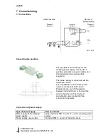
Page 15: ...an angle to either side when snapping onto the pac Note In order to prevent pole reversal during installation the pac elements have been equipped with a keyed connection plug see photo The module is fitted with a matching slot Dismount as described below in b english SITRANS I100 15 Operating instruction A5E02591611 02 The isolating power Supplies may be installed in Zone 2 Zone 22 or outside haza...

Page 16: ...terminal PIN 9 and 7 on the isolating power Terminal PIN 1 and 2 at the terminal set Safe area The pac Bus is an accessory for the isolating power supply It consists of pac Bus elements one per isolator and the terminal set one per pac Bus segment The power supply is connected via the terminals 1 and 2 The signalization of line faults can be read out via the terminal 3 and 4 Please remove one of t...

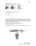
Page 17: ...to the isolating power resistance is present 220Ohm The HART configuration handheld need to be connected at terminal 3 2 1 221 Ohm HART Isolating power supply 12 10 12 11 10 0 4 20mA english SITRANS I100 17 Operating instruction A5E02591611 02 blue terminals PIN 10 11 12 mA source black terminals PIN 1 2 3 A working HART communication requires a minimum load resistance e g input in the output circ...

Page 18: ...or the input and output circuits The line fault detection monitors the common input channel and the according output channel An open output without load leads to fault indication Please connect a load of 250 Ohm to the unused output The DIP switch settings may be changed during operation in Zone 2 as well and in the case of connected intrinsically safe input signals LF1 ON OFF 1 LF1 ON OFF 1 ...

Page 19: ...00 devices may only be executed by the company Siemens Please contact your local Siemens sales office In order to quickly process your request please provide us with the following information Type and serial number Purchase date s Description of the error Application description particularly the configuration of the input output circuitry The devices are maintenance free 10 Accessories and spare p...

Page 20: ...SITRANS I100 20 Operating instruction A5E02591611 02 Control drawing FM ...

Page 21: ...SITRANS I100 21 Operating instruction A5E02591611 02 Control drawing CSA ...

Page 22: ......

Page 23: ......

Page 24: ...ens AG Änderungen vorbehalten Industry Automation IA A5E02591611 02 Sensors and Communication Siemens AG 2010 76181 Karlsruhe DEUTSCHLAND www siemens com processinstrumentation ID Nr 9160613310 Rev2 03 2010 ...

Reviews: