Siemens SITRANS FCT030 Quick Start Manual Download Page 14


SITRANS FCT030 transmitter 

14


A5E03922778-01, 03/2012 
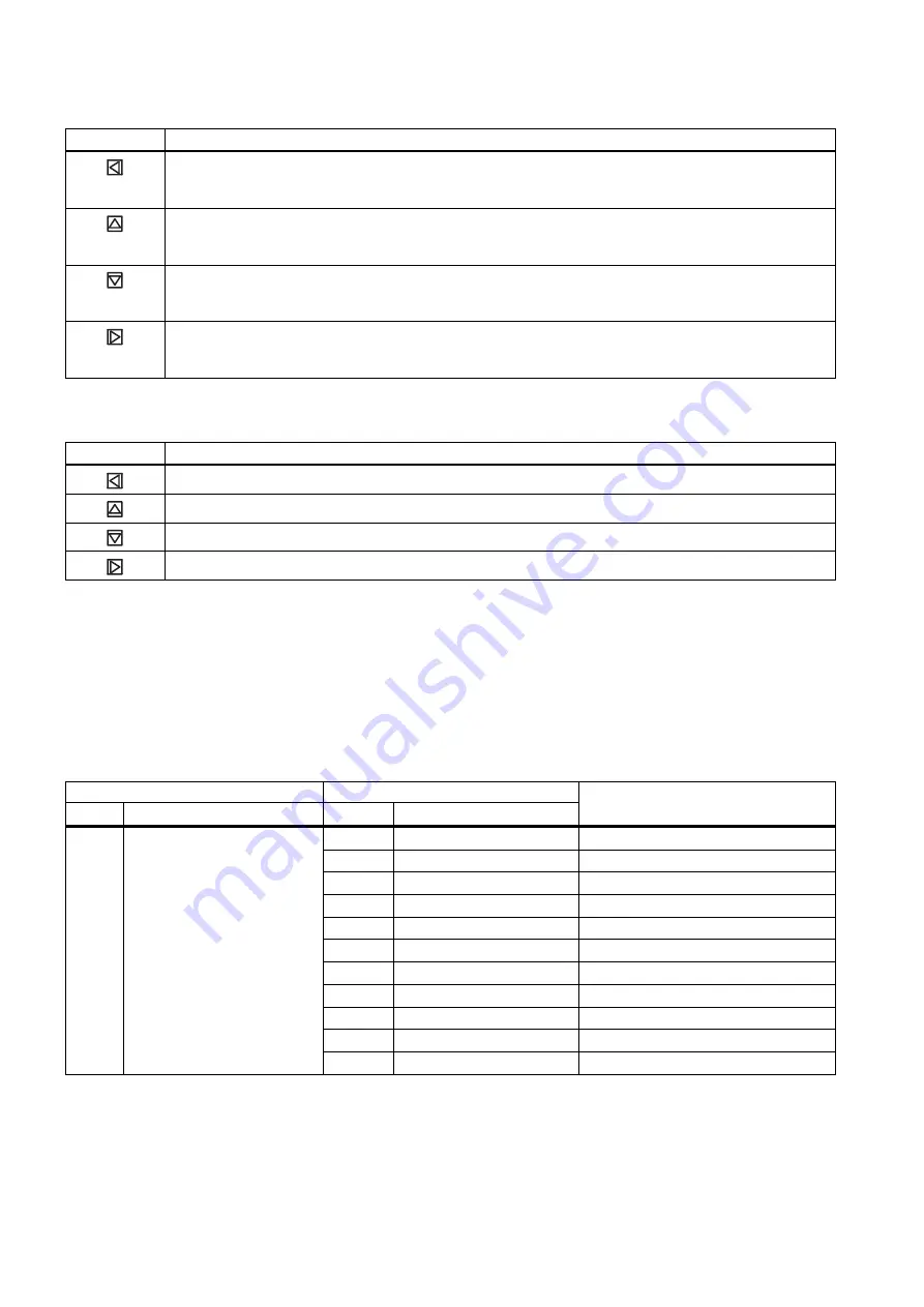
Table 5-6 

Parameter edit view 

Key 

Function 


Select the next left position. 

If the most left position is selected, exit the parameter edit view without confirming the changes. Keep 

pressing the key to jump to the most left position 


Change the selected number/character. 

Numeric characters: increase the number by one (for example from 7 to 8)  

ASCII characters: select the previous character in the alphabet 


Change the selected number/character. 

Numeric characters: decrease the number by one (for example from 8 to 7) 

ASCII characters: select the next character in the alphabet 


Select the next right position. 

If most right position is selected, confirm the change and exit the parameter edit view. Keep pressing the 

key to jump to the most right position 


Table 5-7 

Parameter read only view 

Key 

Function 


Exit parameter edit view 


No functionality 


No functionality 


No functionality 

In the following table the menus are entered in bold text and the parameters in 

italic

Quick start 
The menu items 1.1 through 1.11 make up a quick start guide. 

In the following table only the menus and parameters of the first two levels of the LUI menu structure are listed. 

Table 5-8 

Main menu   

Level 1 

Level 2 

No. 

Name 

No. 

Name 

More information 

1.1 

Flow Direction


1.2 

Process Noise Damping


1.3 

Massflow 

Menu item 1.3: Massflow  

1.4 

Volumeflow 

Menu item 1.4: Volumeflow  

1.5 

Density 

Menu item 1.5: Density  

1.6 

Fluid Temperature 

Menu item 1.6: Fluid temperature  

1.7 

Fraction 

Menu item 1.7: Fraction  

1.8 

Totalizer 1 

Menu item 1.8: Totalizer 1  

1.9 

Totalizer 2 

Menu item 1.9: Totalizer 2  

1.10 

Totalizer 3 

Menu item 1.10: Totalizer 3  

Quick Start 

1.11 

Start Zero Point Adj.


Summary of Contents for SITRANS FCT030

Page 1: ...s proper transport storage positioning and assembly The device must be carefully operated and maintained Only qualified personnel should install or operate this device Items supplied Compact system SITRANS FC430 sensor and compact mounted transmitter Packet of cable glands Quick Start guide CD containing software certificates and device manuals Remote system With M12 connection SITRANS FCS400 sens...

Page 2: ... included parts Note Sensor installation The installation of the FCS400 sensor is described in the SITRANS FCS400 Quick Start A5E03649755 Remote mounting Wall mounting 1 Prepare holes with aid of mounting bracket 2 Fasten mounting bracket with cushion pad to wall torque 10 Nm Pipe mounting 1 Mount mounting bracket with cushion pad on pipe using fastening brackets U bolts and supplied pipe adaptor ...

Page 3: ...emote configuration the transmitter can be turned horizontally and vertically In a compact configuration the transmitter can be turned horizontally only Horizontal rotation 1 Unscrew cap from lock screw 2 Loosen lock screw at transmitter pedestal using 5 mm Allen key 3 Carefully rotate transmitter into desired position r r 4 Firmly tighten lock screw torque 10 Nm 5 Replace cap onto lock screw torq...

Page 4: ...ly be opened by qualified personnel Before removing the terminal cover the auxiliary power must be switched off from all poles Following installation the terminal cover must be screwed back on again 1 Remove blind plugs where required and mount cable glands 2 3 1 Input output connection channels 2 to 4 Power supply connection Current output HART connection channel 1 2 Remove lid lock screw for ter...

Page 5: ...onfiguration Cp Used in current output passive configuration Not used IO2 Signal output active channel 2 positive IO2 Signal output channel 2 common IO2 Signal output channel 2 negative IO3 Input output channel 3 positive IO3 Input output channel 3 common IO3 Input output channel 3 negative IO4 Input output channel 4 positive IO4 Input output channel 4 common IO4 Input output channel 4 negative SI...

Page 6: ...s wiring tool wedge into top slot to spread clamp plates 3 Insert wire 4 Release wiring tool Power supply 1 Flip open power supply terminal protection cover 2 Remove cap and ferrule from cable gland and slide onto cable 3 Push cable through open gland and cable path 4 Restore ferrule and tighten cap to lightly hold cable in place 5 Connect ground to terminal and power to terminals L and N using wi...

Page 7: ...ten cable gland Current output HART channel 1 1 Remove cap and ferrule from cable gland and slide onto cable 2 Push cable through open gland and cable path 3 Restore ferrule and tighten cap to lightly hold cable in place 4 Signal cable screen is folded back over outer sheath and grounded beneath cable clamp 5 Connect wires to terminals using wiring tool SITRANS FCT030 transmitter A5E03922778 01 03...

Page 8: ...e Load Current output channel 1 500 Ω HART 230 Ω Inputs and outputs channels 2 to 4 1 Remove cap and ferrule from cable gland and slide onto cable 2 Push cable through open gland and cable path 3 Restore ferrule and tighten cap to lightly hold cable in place 4 Signal cable screen is folded back over outer sheath and grounded beneath cable clamp 5 Connect wires to terminals using wiring tool SITRAN...

Page 9: ...put If status alarm class alarm number one stage dosing or two stage dosing X X X VLJQDO U0 IOXa IOXp IOXC 8LQW Signal output Passive Analog pulse frequency or status output If status alarm class alarm number one stage dosing or two stage dosing X X X VLJQDO 8H W 8 IOXC IOXa IOXp IOXC IOXa IOXp Signal input Active Start dosing stop dosing reset tot 1 reset tot 2 reset tot 3 reset all totalizers st...

Page 10: ...ly closed Note Load Signal output 500 Ω Relay output 30 V AC DC 100 mA Connection check up 1 Check individual wire installation by tugging firmly 2 Firmly tighten cable glands and insert blanking plugs in unused cable entries 3 Remove o ring from lid 4 Reinstate lid and screw in until mechanical stop Wind back lid by one turn 5 Mount o ring by pulling it over the lid and tighten lid cover until yo...

Page 11: ...p to six operation views The operation views are fully configurable to show different process values in different operation view types Depending on the operation view type configuration the view is either measurement view or alarm view Measurement view Displays the measurement values Alarm view Displays the active alarms in a list Navigation view The navigation view shows the menus and parameters ...

Page 12: ...w level 2 Table 5 3 Alarm view level 2 Key Function Enter alarm view level 1 Select the item above in the list keep pressing the key to accelerate scrolling up the selection list Select the item below in the list keep pressing the key to accelerate scrolling down the selection list Enter alarm view level 3 Table 5 4 Alarm view level 3 Key Function Enter alarm view level 2 No functionality No funct...

Page 13: ...ey to accelerate scrolling up the selection list If the key is pressed when the top item is selected the bottom item will be highlighted Select the item below in the list keep pressing the key to accelerate scrolling down the selection list If the key is pressed when the bottom item is selected the top item will be highlighted Enter the next lower level of the navigation view for example from leve...

Page 14: ...Keep pressing the key to jump to the most right position Table 5 7 Parameter read only view Key Function Exit parameter edit view No functionality No functionality No functionality In the following table the menus are entered in bold text and the parameters in italic Quick start The menu items 1 1 through 1 11 make up a quick start guide In the following table only the menus and parameters of the ...

Page 15: ...Menu item 3 2 Alarms 3 3 Maintenance Menu item 3 3 Maintenance 3 4 Diagnostics Menu item 3 4 Diagnostics 3 5 Characteristics Menu item 3 5 Characteristics 3 6 SensorFlash Menu item 3 6 SensorFlash 3 7 Simulate Menu item 3 7 Simulate 3 8 Self Test Menu item 3 8 Self Test 3 Maintenance Diagnostics 3 9 Dosing Test Menu item 3 9 Dosing Test 4 1 Polling Address SW 4 2 Polling Address HW 4 3 TAG 4 4 HAR...

Page 16: ...ency However the information in this publication is reviewed regularly and any necessary corrections are included in subsequent editions Responsibility for suitability and intended use of this instrument rests solely with the user Copyright Siemens AG 03 2012 All Rights Reserved Technical data subject to change without prior notice Siemens A S Flow Instruments DK 6430 Nordborg www siemens com flow...

Page 17: ...et 上找到 流量文档 http www siemens com flowdocumentation 小心 运输 存储 放置和装配措施必须适当 才能确保设备正确可靠的运行 操作和维护设备时务必小心 只有合格人员可以 安装或操作本设备 供货内容 紧凑型系统 SITRANS FC430 传感器及紧凑型安装变送器 电缆接头包 快速入门指南 包含软件 证书及设备手册的 CD 远程型系统 采用 M12 连接方式 SITRANS FCS400 传感器 装有 M12 插座的 SITRANS FCT030 变送器 安装支架和垫片 带有 M12 连接器的传感器电缆 电缆接头包 快速入门指南 包含软件 证书及设备手册的 CD Siemens 保留所有权利 Ⓟ 2012 A5E03922778 01 03 2012 17 ...

Page 18: ...设备手册的 CD 说明 交付内容根据版本及附加件而有所变化 产品包装内的内容列表会列出所有随附零件 说明 传感器安装 FCS400 传感器的安装在 SITRANS FCS400 快速入门 A5E03649755 中有描述 远程安装 墙式安装 1 借助安装支架打孔 2 将带有垫片的安装支架固定到墙上 扭矩为 10 Nm 管道安装 1 使用紧固支架 U 形螺栓和随附的管接头将带有垫片的安装支架安装到管道上 注意 U 形螺栓和其它五金器具不随流量计 一并提供 2 紧固螺母 扭矩 10 Nm SITRANS FCT030 变送器 18 A5E03922778 01 03 2012 ...

Page 19: ...合 3 拧紧安装支架上的螺丝 扭矩 25 Nm 转动变送器 在远程配置中 变送器可水平或垂直转动 在紧凑配置中 变送器只能水平转动 水平旋转 1 从锁紧螺丝上拧下螺丝帽 2 使用 5 mm 内六角扳手松开变送器基座上的锁紧螺丝 3 小心地将变送器旋转至所需位置 r r 4 拧紧锁紧螺丝 扭矩 10 Nm 5 将螺丝帽放回锁紧螺丝 扭矩 10 Nm 垂直旋转 1 转动三圈安装支架末端的固定帽以将其松开 SITRANS FCT030 变送器 A5E03922778 01 03 2012 19 ...

Page 20: ... 拧紧固定帽 扭矩 25 Nm 连接 警告 只要设备通电 就只有合格人员才能在传感器连接区域上打开外壳盖 在取下端子盖前 必须从所有电极处断开辅助电源 安装后 必须再次拧回端子盖 1 如果需要 取下空插头 然后安装电缆接头 2 3 1 输入 输出连接 通道 2 到 4 电源连接 电流输出 HART 连接 通道 1 2 取下端子连接盖上的机盖锁紧螺丝 3 取下端子连接盖 SITRANS FCT030 变送器 20 A5E03922778 01 03 2012 ...

Page 21: ...a 用于电流输出主动模式 C 用于电流输出主动和被动模式 Cp 用于电流输出被动模式 未使用 IO2 信号输出主动通道 2 正向 IO2 信号输出通道 2 公共 IO2 信号输出通道 2 反向 IO3 输入 输出通道 3 正向 IO3 输入 输出通道 3 公共 IO3 输入 输出通道 3 反向 IO4 输入 输出通道 4 正向 IO4 输入 输出通道 4 公共 IO4 输入 输出通道 4 反向 SITRANS FCT030 变送器 A5E03922778 01 03 2012 21 ...

Page 22: ...22778 01 03 2012 接线工具 使用接线工具连接电缆 接线工具位于应用端子区域 接线工具位置 1 将接线工具的钩子插入接收器槽内 2 将接线工具楔压入顶槽以展开夹板 3 插入电线 4 松开接线工具 电源 1 翻开电源端子保护盖 2 从电缆接头取下盖帽和套圈 然后滑到电缆上 3 将电缆穿过打开的接头和电缆路径 4 将套圈放回原位 然后拧紧盖帽 轻轻地将电缆固定到位 5 按照下图右侧所示 使用接线工具将地线连接到端子 并将电源连接到端子 L 和 N ...

Page 23: ...15 47 到 63 Hz 1 1 电源 24 到 90 V DC 20 20 6 用夹条固定电缆 7 关闭并闭锁电源端子保护盖 8 拧紧电缆接头 电流输出 HART 通道 1 1 从电缆接头取下盖帽和套圈 然后滑到电缆上 2 将电缆穿过打开的接头和电缆路径 3 将套圈放回原位 然后拧紧盖帽 轻轻地将电缆固定到位 4 将信号电缆屏蔽向后折叠到外护套上并在电缆夹下方接地 5 使用接线工具将电线连接到端子 SITRANS FCT030 变送器 A5E03922778 01 03 2012 23 ...

Page 24: ...C 8LQW ℊ 8H W 8 Ca Cp C 6 拧紧电缆接头 说明 在订货时预选主动或被动电流输出 说明 负载 电流输出 通道 1 500 Ω HART 230 Ω 输入和输出 通道 2 到 4 1 从电缆接头取下盖帽和套圈 然后滑到电缆上 2 将电缆穿过打开的接头和电缆路径 3 将套圈放回原位 然后拧紧盖帽 轻轻地将电缆固定到位 4 将信号电缆屏蔽向后折叠到外护套上并在电缆夹下方接地 5 使用接线工具将电线连接到端子 SITRANS FCT030 变送器 24 A5E03922778 01 03 2012 ...

Page 25: ...Xa IOXp IOXC 8LQW 信号输出 被动 模拟 脉冲 频率 或状态输出 如果状态为 报警 级别 报警号 一 级给料或二级给料 X X X 8H W 8 IOXC IOXa IOXp IOXC IOXa IOXp 信号输入 主动 开始给料 停止给 料 复位累加器 1 复位累加器 2 复位累加器 3 复位所有累加 器 开始零点调 整 暂停 继续给 料 强制输出或冻 结输出 X X U0 IOXa IOXp IOXC 8LQW ℊ 信号输入 被动 开始给料 停止给 料 复位累加器 1 复位累加器 2 复位累加器 3 复位所有累加 器 开始零点调 整 暂停 继续给 料 强制输出或冻 结输出 X X 8H W 8 IOXC IOXa IOXp IOXC IOXa IOXp ℊ SITRANS FCT030 变送器 A5E03922778 01 03 2012 25 ...

Page 26: ...出 报警级别 报警 号 一级给料或二 级给料 X X IOXa IOXp IOXC 常闭 说明 负载 信号输出 500 Ω 继电器输出 30 V AC DC 100 mA 连接检查 1 通过拉紧来检查各条电线的安装 2 拧紧电缆接头 然后将堵塞插头插入未使用的电缆入口 3 从机盖上取下 O 形环 4 将机盖按原状恢复并拧入螺丝 直到机械固定为止 将机盖倒转一圈 5 通过拉动 O 形环将其盖在机盖上来安装 O 形环 然后拧紧机盖直到感觉 O 形环两侧都有摩擦为止 将机盖转动四分之一 圈 以密封 O 形环 6 复原并拧紧随附的机盖锁紧螺丝 7 紧邻电缆接头之前创建一个滴水圈 使电缆向下弯曲 以确保水分不会渗入到电子设备机壳内部 ...

Page 27: ...使用的安全性 使用菜单结构 有三种视图类型 操作视图 操作员视图最多可显示六个操作视图 操作视图完全可组态 以显示不同操作视图类型的不同过程值 根据操作视图类 型配置 视图为测量视图或报警视图 测量视图 显示测量值 报警视图 在列表中显示活动报警 导航视图 导航视图显示菜单和参数 导航视图用于在设备中导航至菜单和参数 参数视图 参数视图可从导航视图进入 参数视图用于查看和编辑参数 导航操作视图 使用如下控制按钮浏览操作视图和菜单项 表格 5 1 测量视图 按键 功能 无功能 转到操作视图中的上一菜单 转到操作视图中的下一菜单 进入导航视图 SITRANS FCT030 变送器 A5E03922778 01 03 2012 27 ...

Page 28: ...进入报警视图级别 2 表格 5 3 报警视图级别 2 按键 功能 进入报警视图级别 1 在列表中选择上方项目 按住该按键可加速向上滚动选择列表 在列表中选择下方项目 按住该按键可加速向下滚动选择列表 进入报警视图级别 3 表格 5 4 报警视图级别 3 按键 功能 进入报警视图级别 2 无功能 无功能 无功能 下图显示了在启用测量视图 1 3 和 4 以及报警视图 5 的情况下如何在测量视图和报警视图之间导航的示例 SITRANS FCT030 变送器 28 A5E03922778 01 03 2012 ...

Page 29: ... 功能 进入下一更高级别的导航视图 例如 从级别 2 到级别 1 如果已位于导航视图级别 1 则进入操作视图 在列表中选择上方项目 按住该按键可加速向上滚动选择列表 如果在选中顶部项目时按下该键 底部项 目将会突出显示 在列表中选择下方项目 按住该按键可加速向下滚动选择列表 如果在选中底部项目时按下该键 顶部项 目将会突出显示 进入下一更低级别的导航视图 例如 从级别 1 到级别 2 如果在导航视图中选择参数 则进入参数视图 编辑参数 图形中显示此符号 时 菜单界面上的四个按钮用于更改参数 如下所述 SITRANS FCT030 变送器 A5E03922778 01 03 2012 29 ...

Page 30: ...字符 选择下一个右侧位置 如果选择最右侧的位置 则确认更改并退出参数编辑视图 按住该按键可跳转到最右侧的位置 表格 5 7 参数只读视图 按键 功能 退出参数编辑视图 无功能 无功能 无功能 下表中 用粗体文本表示菜单 用斜体表示参数 快速启动 菜单项 1 1 到 1 11 是快速入门指南 下表中 仅列出 LUI 菜单结构中前两个级别的菜单和参数 表格 5 8 主菜单 级别 1 级别 2 编号 名称 编号 名称 更多信息 1 1 流向 1 2 过程噪声抑制 1 3 质量流量 菜单项 1 3 质量流量 1 4 体积流量 菜单项 1 4 体积流量 1 5 密度 菜单项 1 5 密度 1 6 流体温度 菜单项 1 6 流体温度 1 7 分数 菜单项 1 7 分数 1 8 累加器 1 菜单项 1 8 累加器 1 1 9 累加器 2 菜单项 1 9 累加器 2 1 10 累加器 3 菜单项 1 10...

Page 31: ...单项 2 8 显示 3 1 标识 菜单项 3 1 标识 3 2 报警 菜单项 3 2 报警 3 3 维护 菜单项 3 3 维护 3 4 诊断 菜单项 3 4 诊断 3 5 特性 菜单项 3 5 特性 3 6 SensorFlash 菜单项 3 6 传感器闪存 3 7 模拟 菜单项 3 7 模拟 3 8 自测 菜单项 3 8 自测 3 维护与诊断 3 9 给料测试 菜单项 3 9 给料测试 4 1 轮询地址 SW 4 2 轮询地址 HW 4 3 标签 4 4 HART 设备类型 4 5 HART 版本 4 6 变量绘制 菜单项 4 6 变量绘制 4 通信 4 7 HART 单位 菜单项 4 7 HART 单位 5 安全 5 1 访问管理 菜单项 5 1 访问管理 6 Language SITRANS FCT030 变送器 A5E03922778 01 03 2012 31 ...

Page 32: ...Flow Instruments DK 6430 Nordborg www siemens com flow 我们已经查阅了此手册的内容以保证与所描述硬件的一致性 由于无法完全排除未来的变化情况 因此我们 无法保证绝对一致性 尽管如此 此手册中的信息会被定期审查 以后版本中将包括所有必需的修改内容 使用者须对仪表的配套使用和用途负全责 版权 西门子股份有限公司 03 2012 版权所有 保留修改权 SITRANS FCT030 变送器 A5E03922778 03 2012 ...

Reviews: