Functions
2.10 Restricted Earth Fault Protection (optional)
SIPROTEC, 7SD5, Manual
C53000-G1176-C169-5, Release date 02.2011
266
2.10.2
Functional Description
Measuring principle
During normal operation, no starpoint current
I
SP
flows through the starpoint lead. The sum of the phase cur-
rents 3
I
0
=
I
L1
+
I
L2
+
I
L3
approximates zero.
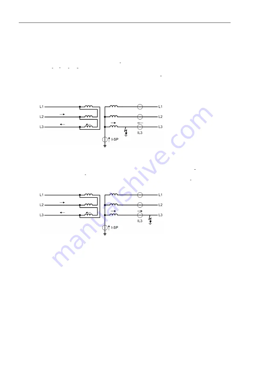
When an earth fault occurs in the protected zone, a starpoint current
I
SP
will flow; depending on the earthing
conditions of the power system a further earth current may be recognized in the residual current path of the
phase current transformers (dashed arrow in Figure 2-132), which is, however, more or less in phase with the
starpoint current. The current direction into the protected object is defined as positive.
Figure 2-132
Example for an earth fault in a transformer with current distribution
When an earth fault occurs outside the protected zone (Figure 2-133), a starpoint current
I
SP
will also flow. But
an equally large current 3
I
0
must then flow through the phase current transformers. Since the current direction
into the protected object is defined as positive, this current is in phase opposition with
I
SP
.
Figure 2-133
Example for an earth fault outside a transformer with current distribution
When an external non-earthed fault causes heavy currents to flow through the protected zone, differences in
the magnetic characteristics of the phase current transformers under conditions of saturation may cause a sig-
nificant summation current which could resemble an earth current flowing into the protected zone. Measures
must be taken to prevent this current from causing a trip. For this, the restricted earth fault protection provides
stabilization methods which differ strongly from the usual stabilization methods of differential protection
schemes since it considers both the magnitude of the measured currents and their direction (phase relation-
ship).


