Functions
2.5 Distance Protection
SIPROTEC, 7SD5, Manual
C53000-G1176-C169-5, Release date 02.2011
160
even when there is additional infeed via the tee point. The delay times are set in accordance with the type of
application, usually to zero or a very small delay. When used in conjunction with teleprotection comparison
schemes, the dependence on the fault detection must be considered (refer to margin heading „Distance Pro-
tection Prerequisites“ in Section 2.7.14).
If the distance protection is used in conjunction with the internal or an external automatic reclose function, you
can determine which distance stage is released prior to starting the AR in address
1657
1st AR -> Z1B
.
Normally the measurement takes place before the first protection trip in the first reclose cycle with overreaching
zone Z1B. (
1st AR -> Z1B
=
YES
). This can be suppressed by setting
1st AR -> Z1B
to
NO
. In this case
overreaching zone Z1B is not released when the reclose function is ready. Zone Z1 is always released, unless
it is blocked by a binary input or in differential protection mode. With an external automatic reclose device the
setting only has an effect when the service condition of this device is input via binary input
„>Enable
ARzones“
(No. 383).
Minimum Current of Zone Z1
In earthed systems with parallel lines and single-side starpoint earthing, it can be necessary to enable tripping
of Z1 only above an increased phase current threshold value.For this purpose, you can define a separate
minimum current for the zone Z1 under address
1608
Iph>(Z1)
. The pickup of zone Z1 is in this case only
possible if the phase currents exceed this threshold value and are also above the threshold for enabling the
distance measurement (
1502
Minimum Iph>
,
1910
Iph>>
,
1911
Iph>
,
1916
Iphi>
).
Parameter
1608
Iph>(Z1)
is only visible and effective if the address
119
Iph>(Z1)
is set to
Enabled
. The
use of a separate minimum current for Z1 is only recommended if the power system constellation has been
checked by calculations.
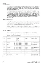
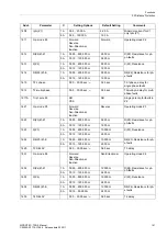
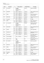
2.5.2.3
Settings
Addresses which have an appended "A" can only be changed with DIGSI, under Additional Settings.
The table indicates region-specific presettings. Column C (configuration) indicates the corresponding second-
ary nominal current of the current transformer.
Addr.
Parameter
C
Setting Options
Default Setting
Comments
1601
Op. mode Z1
Forward
Reverse
Non-Directional
Inactive
Forward
Operating mode Z1
1602
R(Z1) Ø-Ø
1A
0.050 .. 600.000
Ω
1.250
Ω
R(Z1), Resistance for ph-
ph-faults
5A
0.010 .. 120.000
Ω
0.250
Ω
1603
X(Z1)
1A
0.050 .. 600.000
Ω
2.500
Ω
X(Z1), Reactance
5A
0.010 .. 120.000
Ω
0.500
Ω
1604
RE(Z1) Ø-E
1A
0.050 .. 600.000
Ω
2.500
Ω
RE(Z1), Resistance for ph-
e faults
5A
0.010 .. 120.000
Ω
0.500
Ω
1605
T1-1phase
0.00 .. 30.00 sec;
∞
0.00 sec
T1-1phase, delay for
single phase faults
1606
T1-multi-phase
0.00 .. 30.00 sec;
∞
0.00 sec
T1multi-ph, delay for multi
phase faults
1607
Zone Reduction
0 .. 45 °
0 °
Zone Reduction Angle
(load compensation)

