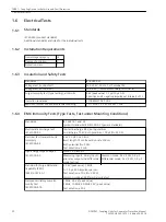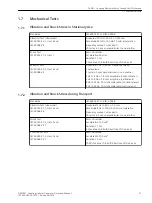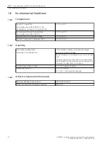
Technical Data
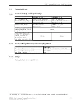
Auxiliary Voltage and Output Ratings
Terminals 1A – 2A
Terminals 2A – 3A
Rated auxiliary voltage
100 to 125 V AC, 50/60 Hz (1)
230 V AC, 50/60 Hz (2)
Permissible auxiliary voltage
80 to 144 V AC, 45 to 65 Hz
176 to 265 V AC, 45 to 65 Hz
Terminals 4A – 6A
Terminals 4A – 5A
Nominal output voltage
39 to 49 V AC for (1)
43 V AC for (2)
58 to 74 V AC for (1)
64 V AC for (2)
Continuous output current (1B –
3B shorted to ground, without
choke L1)
100 mA
Output current for max. 30
minutes (1B – 3B shorted to
ground, with choke L1)
Recovery time 60 min
Max. power consumption 22 W
175 mA
200 mA
Load Capability of the Capacitive Coupling Circuit
Terminals 1B – 3B
Max. permissible continuous voltage
1000 V DC + 250 V peak value (max. 300 Hz)
1
Max. permissible continuous current
500 mA RMS
1
Max. dissipated power
60 W
Weight
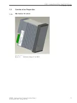
The weight of the device is 5.6 kg (12.4 lb.).
1.5
1.5.1
1.5.2
1.5.3
1
The RMS voltage and current over the resistors R1 ( 2x 100 Ω) must be measured to avoid exceeding 50 W of power dissipation.
7XR81 – Coupling Device for Rotor Ground-Fault Protection
1.5 Technical Data
SIPROTEC, Coupling Units for Generator Protection, Manual
19
C53000-H5040-C072-1, Edition 09.2018

