2.4 Time Overcurrent Protection for Phase and Residual Currents
173
7UT613/63x Manual
C53000-G1176-C160-2
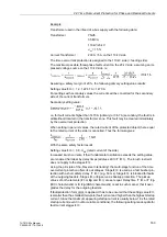
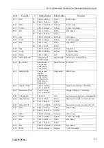
In address
2202
InRushRest. 3I0
inrush restraint (inrush restraint with 2nd har-
monic) is enabled or disabled. Set
ON
if the residual current stage of the time overcur-
rent protection is applied at the supply side of a transformer whose starpoint is
earthed. Otherwise, retain setting
OFF
. If you set a very small pickup value, consider
that the inrush restraint function cannot operate below 10 % nominal current (lower
limit of harmonic filtering).
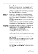
High Set Current
Stage 3I0>>
If stage
3I0>>
(address
2211
or
2212
) is combined with the 3I0> stage or the 3I0p
stage, a two-stage characteristic will be the result. If one stage is not required, the
pickup value has to be set to
∞
. Stage
3I0>>
always operates with a defined delay.
If the protected winding is not earthed, zero sequence current only emerges due to an
inner earth fault or double earth fault with one inner base point. Here, the 3I0>> stage
is usually not required.
The 3I0>> stage can, for example, be applied for current grading. Please note that the
zero sequence system of currents is of importance. For transformers with separate
windings, zero sequence systems are usually kept separate (exception: bilateral star-
point earthing or earthed auto-transformer).
Inrush currents can only be created in zero sequence systems if the starpoint of the
respective winding is earthed. If the fundamental exceeds the setting value, the inrush
currents are rendered harmless by delay times (address
2213
T 3I0>>
).
„Reverse Interlocking“ is only sensible if the respective winding is earthed. In that
case, the multi-stage function of the time overcurrent protection is beneficial: For ex-
ample, stage
3I0>>
is used as fast busbar protection with a short safety delay
T
3I0>>
(e.g. 50 ms). Stage
3I0>>
is blocked for faults at the outgoing feeders. Stages
3I0>
or
3I0p
serve as backup protection. The pickup values of both elements (
3I0>
or
3I0p
and
3I0>>
) are set equal. Delay time
T 3I0>
or
T 3I0p
(IEC characteristic)
or
D 3I0p
(ANSI characteristic) is set in such manner that it overgrades the delay for
the outgoing feeders. Here, the grading coordination chart for earth faults, which
mostly allows shorter setting times, is of primary importance.
The set time
T 3I0>>
is an additional delay time and does not include the operating
time (measuring time, etc.). The delay can be set to
∞
. If set to infinity, the pickup of
this function will be indicated but the stage will not trip after pickup. If the pickup thresh-
old is set to
∞
, neither a pickup annunciation nor a trip is generated.
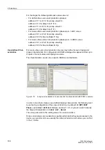
Definite Time Over-
current Stage3I0>
The minimum appearing earth fault current is relevant for the setting of the time over-
current stage
3I0>
(address
2214
or
2215
). Please note that, in case of various mea-
suring locations, higher measuring tolerance may occur due to summation errors.
The time delay to be set (parameter
2216
T 3I0>
) is derived from the grading coor-
dination chart created for the network. For earth currents with earthed network, a sep-
arate grading coordination chart with shorter delay times can be set up. If you set a
very small pickup value, it must be taken into consideration that the inrush restraint
function cannot operate below 10 % nominal current (lower limit of harmonic filtering).
An adequate time delay could be reasonable if inrush restraint is used.
The set time is an additional delay time and does not include the operating time (mea-
suring time, etc.). The delay can also be set to
∞
. If set to infinity, the pickup of this
function will be indicated but the stage will not trip after pickup. If the pickup threshold
is set to
∞
, neither a pickup annunciation nor a trip is generated.
Summary of Contents for SIPROTEC 7UT613 series
Page 16: ...Contents 16 7UT613 63x Manual C53000 G1176 C160 2 Literature 631 Glossary 623 Index 633 ...
Page 30: ...1 Introduction 30 7UT613 63x Manual C53000 G1176 C160 2 ...
Page 506: ...A Appendix 506 7UT613 63x Manual C53000 G1176 C160 2 7UT633 D E ...
Page 508: ...A Appendix 508 7UT613 63x Manual C53000 G1176 C160 2 7UT633 P Q ...
Page 510: ...A Appendix 510 7UT613 63x Manual C53000 G1176 C160 2 7UT635 D E ...
Page 512: ...A Appendix 512 7UT613 63x Manual C53000 G1176 C160 2 7UT635 P Q ...
Page 515: ...A 2 Terminal Assignments 515 7UT613 63x Manual C53000 G1176 C160 2 7UT633 B ...
Page 517: ...A 2 Terminal Assignments 517 7UT613 63x Manual C53000 G1176 C160 2 7UT633 N ...
Page 519: ...A 2 Terminal Assignments 519 7UT613 63x Manual C53000 G1176 C160 2 7UT635 B ...
Page 521: ...A 2 Terminal Assignments 521 7UT613 63x Manual C53000 G1176 C160 2 7UT635 N ...
Page 622: ...A Appendix 622 7UT613 63x Manual C53000 G1176 C160 2 ...
Page 632: ...Literature 632 7UT613 63x Manual C53000 G1176 C160 2 ...

