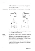
Unbalanced Load (Negative Sequence) Protection (ANSI 46)
67
7UM62 Manual
C53000-G1176-C149-3
Logic
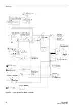
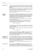
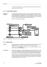
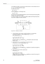
Figure 2-22 shows the logic diagram of the unbalanced load protection. The protection
may be blocked via a binary input (”
”). Pickups and time stages are reset
and the metered values in the thermal model are cleared. The binary input ”
” only serves to clear metered values of the thermal characteristic.
2.10.2 Setting Hints
General
The unbalance load protection is only effective and accessible if it was selected at
address
=
Enabled
within the framework of project
configuration. Set
Disabled
if the function is not required.
The function can be switched
ON
or
OFF
at address
. As an
alternative, the user can only block the trip signal (
Block Relay
).
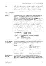
The maximum permissible, constant negative phase-sequence current is required by
the thermal model. For machines of up to 100 MVA with non-salient pole rotors, this
current typically amounts to a value in a range from 6 % to 8 %. With salient-pole
rotors, it is at least 12 % of the nominal machine current. For larger machines and in
cases of doubt, please observe the instructions of the machine manufacturer.
It is important to ensure that the values given by the manufacturer represent the
primary values of the machine. For example, if the long-time allowable thermal inverse
current —with respect to the nominal machine current — is given, this value must
be used to calculate the settings for the unbalanced load time-overcurrent element.
For the settings on the protective relay, this information is converted to the secondary
inverse current. For this situation
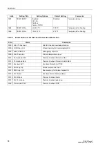
Pickup Threshold /
Warning Stage
The value for
is set at address
. It is at the same time the pickup value for a
current warning stage the delay time for which
is set at address
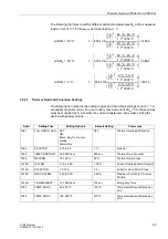
Example:
Negative Sequence
Factor K
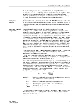
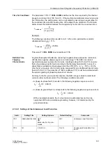
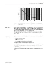
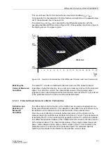
If the machine manufacturer has indicated the loadability duration due to an
unbalanced load by means of the constant K = (I
2
/I
N
)
2
⋅
t, it is set immediately at the
address
. The constant K is proportional to the permissible energy
loss.
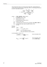
where
I
2 max prim
Permissible long-term thermal inverse current of the
machine
I
N Machine
Nominal machine current
I
N CT prim
Nominal primary CT current
I
2max prim
I
N Machine
------------------------
è
ø
æ
ö
I
N Machine
I
N CT prim
------------------------
⋅
Pickup Setting
=
Machine:
I
N Machine
= 483 A
I
2 perm prim
/ I
N Machine
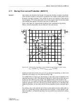
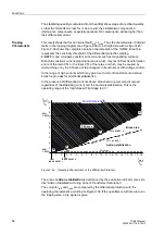
= 11 % continuous (salient-pole
machine, see Figure 2-23)
Current
transformer:
I
N CT prim
= 500 A
Setting value
I
2 perm.
= 11 % · (483 A/500 A) = 10.6 %


