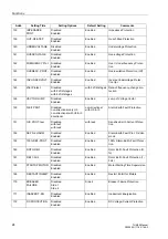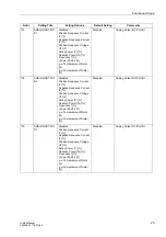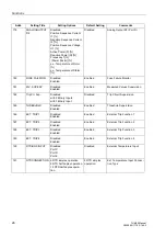
Functions
16
7UM62 Manual
C53000-G1176-C149-3
2.1
Introduction, Reference Power System
The following chapters explain the individual protective and additional functions and
provide information about on the setting values.
Generator
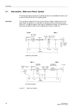
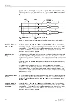
The calculation examples are based on two reference power systems with the two
typical basic connections, i.e. the busbar connection and the unit connection (see
Figure 2-1). All default settings of the relay are adapted accordingly. The allocation of
measured quantities to side 1 and 2 respectively is shown in Figure 2-1.
Figure 2-1
Reference Systems
7UM62
7UM62
G
a) Busbar connection
b) Unit connection
U
E
I
L, S2
I
EE1
U
L
6.3 kV
√
3
/
500 V
500 A/1 A
5.27 MVA
6.3 kV
6.3 kV
√
3
100 V
√
3
5.3 MVA
20 kV/6.3 kV
20 kV
I
L, S2
U
L
U
E
I
EE
500 A/1 A
5.27 MVA
6.3 kV
6.3 kV
√
3
100 V
√
3
3
∼
100 V
3
60/1 A
R
L
Earthing
trans-
G
3
∼
I
L, S1
I
L, S1
Side 2
Side 1
Side 2
Side 1
former


