Overvoltage Protection (ANSI 59)
151
7UM62 Manual
C53000-G1176-C149-3
2.20
Overvoltage Protection (ANSI 59)
General
Overvoltage protection serves to protect the electrical machine, and the associated
electrical plant connected to it, from the effects of impermissible voltage increases.
Overvoltages can be caused by incorrect manual operation of the excitation system,
faulty operation of the automatic voltage regulator, (full) load shedding of a generator,
separation of the generator from the system or during island operation.
2.20.1 Functional Description
By means of the overvoltage protection feature, the user can select if he wants to
monitor the phase-to-phase voltages or the phase-earth-voltages. In case of a high
overvoltage, the switchoff is performed with a short-time delay, whereas in case of
lower overvoltages, the switchoff is performed with a longer time delay. In this way,
the voltage regulator can take the voltage back into the nominal range. The user can
specify the voltage limit values and the time delays individually for both stages.
Each stage can be blocked individually and/or both stages can be blocked in common
via binary input(s).
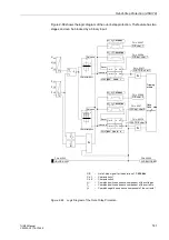
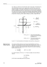
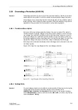
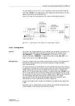
Figure 2-72 shows the logic diagram of the overvoltage protection.
Figure 2-72
Logic Diagram of the Overvoltage Protection
2.20.2 Setting Hints
General
The overvoltage protection is only effective and accessible if it has been set during the
configuration of the protective functions (Section 2.2) at address
,
=
Enabled
. Set
Disabled
if the function is not required. Address
is used to switch the function
ON
or
OFF
, or to block only the trip
command (
Block Relay
).
FNo. 06513
FNo. 06568
&
Pickup U>>
Pickup U>
FNo. 06516
FNo. 06517
&
Tripping
matrix
FNo. 06570
FNo. 06573
FNo. 06566
FNo. 06571
TMin
TRIP CMD

