Functions
128
7UM62 Manual
C53000-G1176-C149-3
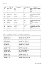
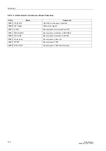
2.17.2 Setting Hints
General
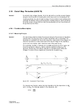
The machine impedance detection is only effective and accessible if it was previously
set within the framework of project configuration (Section 2.2) at address
,
=
Enabled
. Set
Disabled
if the function is not required.
Address
is used to switch the function
ON
and
OFF
, or to
block only the trip command (
Block Relay
).
Pickup
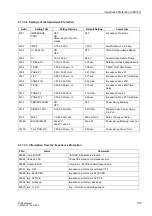
The maximum load current during operation is the most important criterion to be
considered when setting the overcurrent pickup. A pickup by an overload must be
excluded in any case! For this reason, the
pick-up value must be set
above the maximum (over) load current to be expected. Recommended setting: 1.2 to
1.5 times the nominal machine current. The pickup logic corresponds to the logic of
the UMZ I> definite time-overcurrent protection.
If the pickup is derived from the generator terminals and if, for this reason, the short
circuit can fall below the pickup value (address
) due to the collapsing voltage,
the undervoltage seal-in feature is used, i.e. the address
is
switched
ON
.
The undervoltage seal-in feature
U<
(address
) is set to a value below the lowest
phase-to-phase voltage occurring during operation, e.g. to
= 75 % to 80 % of the
nominal voltage. The seal-in time (address
) must exceed the
maximum fault clearance time in a back-up case (recommended setting: address
+ 1 s).
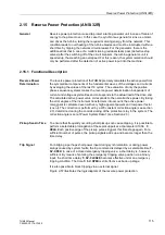
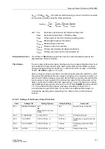
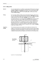
Impedance Stages
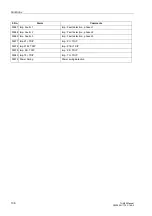
As illustrated in figure 2-60, the protection has the following characteristics which may
be set independently:
−
1st zone (Z1 instantaneous zone) with the setting parameters
Reactance = reach,
= 0 or short delay, if required.
−
Z1B overreach zone, externally controlled via binary input, with the setting
parameters
Reactance = reach,
T1B = 0 or short delay, if required.
−
2nd zone (Z2 zone) with the setting parameters
Reactance = reach,
The user must select a value for T2 which is situated above the
grading time of the network protection.
−
Non-directional final stage with the setting parameter
The user must select a value for T END which ensures that the 2nd
or 3rd stage of the series-connected power system distance
protection is overreached.
As the user can proceed on the assumption that the impedance protection measuring
influences the unit transformer, it must be ensured that the parameterization selection
sufficiently considers the transformer control range.
Therefore,
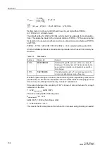
is normally set to a reach of approx. 70 % of the protected zone
(i.e. about 70 % of the transformer reactance), with no or only a small delay (i.e.
= 0.00 s to 0.50 s). In this case, the protective relay will switch off faults on this distance

