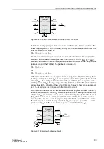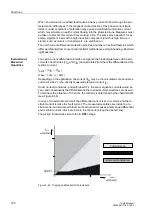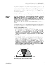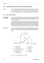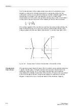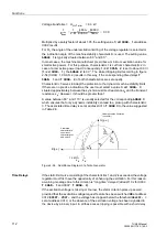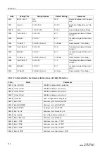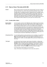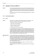
Underexcitation (Loss-of-Field) Protection (ANSI 40)
113
7UM62 Manual
C53000-G1176-C149-3
This feature is set at address
. The following messages and trip
commands are typically assigned:
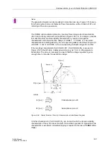
Note: If very short time delays are selected, dynamic balancing procedures may cause
unwanted operations. For this reason, it is recommended to set time values of 0.05 s
or higher.
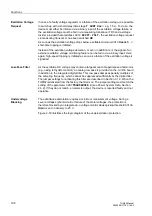
Excitation Voltage
Request
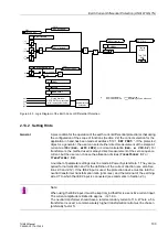
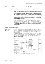
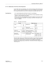
The excitation voltage monitoring feature is set to approx. 50 % of the no-load excita-
tion voltage. If the generator is used for phase-shifting, an even lower threshold must
be chosen, depending on the application in had. It should also be noted that normally
a voltage divider is connected between the device and the excitation voltage.
where U
Exc
No-load excitation voltage,
k
VD
Transformation ratio of voltage divider
Example:
U
Exc N
= 110 V
U
Exc 0
= 40 V
k
VD
= 10: 1
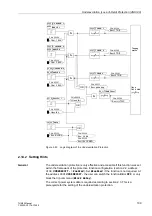
2.14.2.1 Settings of the Underexcitation (Loss-of-Field) Protection
Table 2-6
Setting the Underexcitation Protection
Characteristic 1 and 2 static
stability
not delayed
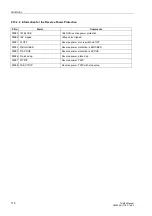
Annunciation:
Err < PU
Characteristic 1 and 2 static
stability
long-time delayed
=
≈
10 s
Trip
Exc<1 TRIP / Exc<2 TRIP
Characteristic 1 and 2
excitation voltage failure
short–time delayed
≈
1.5 s
Trip
Exc< Uexc < TRIP
Characteristic 3
dynamic stability
short–time delayed
≈
0.5 s
Trip
Exc<3 TRIP
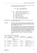
Setting
x
U Exc <
0.50
U
Exc 0
k
U
----------------
V
[ ]
⋅
≈
Setting U Exc <
0.50
40 V
10
------------
⋅
≈
= 2.0 V (address
3013
)
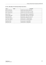
Addr.
Setting Title
Setting Options
Default Setting
Comments
3001
UNDEREXCIT.
OFF
ON
Block relay for trip com-
mands
OFF
Underexcitation Protection
3011
T SHRT Uex<
0.00..60.00 sec;
∞
0.50 sec
T-Short Time Delay (Char. &
Uexc<)

